|
Current Time:
|
|
|
|
|
Gerry's Electronics & Robotics Laboratory -=SOLDERING=- -=MY BENCH=- -=MY ROBOTS=- -=PCB FAB=- -=CHIPPERY=- |
|
-= WELCOME TO GERRY'S ROBOTICS PAGE =- -=ER-III=- -=ER-4PC=- -=CRS PLUS=- -=CRS A250=- -=PNEUMATICS=-
|
||
-=CRS ROBOTIC ARM YAHOO GROUP =- Please Join my CRS ROBOTIC ARM Yahoo Group! Let's all connect and share our Resources to get our CRS Robots up and running. http://groups.yahoo.com/group/CRS_ROBOTIC-ARM_GROUP
-= CRSPLUS Robot Arm & Controller Systems =- There are several versions of the CRSPlus Robot & controller systems that have been released. It is important to confirm which system you have. Some of the Models avaialbe are shown below: * SRS-M1 * SRS-M1A * RSC-M1 * RSC-M1A * A150 * A250 * A251
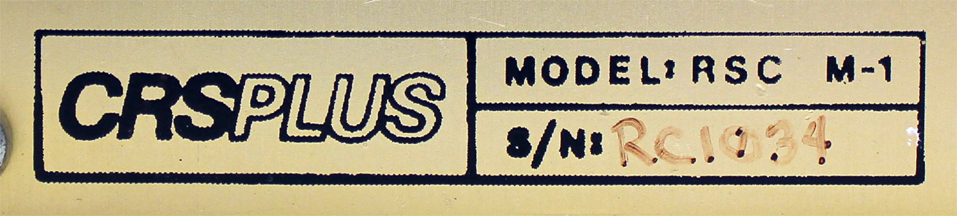
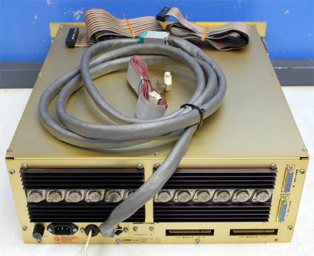
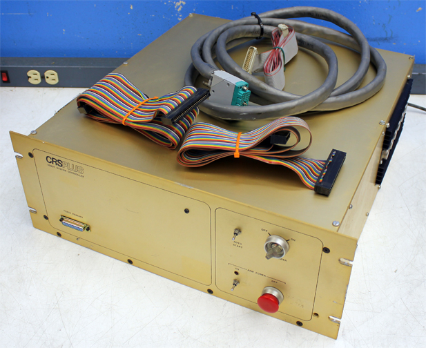
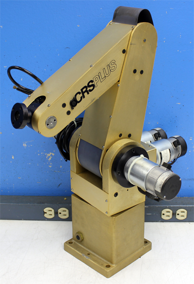
MODEL "RSC-M1" CONTROLLER & ROBOT
Notice the visible Difference between the "RSC-M1" and the "SRS-M1A". First off, the Controller is completely different. It has the Drive Transitor Heat Sinks bolted directly to the side and Back of the Controller enclosure. Also, the Robot Base color is Different between systems. For the RSC-M1, the Base color is a BRASS, and for the SRS-M1A, the Robot base is Black. Notice as well that the EDAC Connector on the Robot Base is a Light Green color for the RSC-M1.
MODEL "A150" CONTROLLER
I am still looking for better pictures of the A150 and A250 Robot Systems, and Technical manuals as well. So if you have access to them or if you can point me in the right direction to acquire them, please Contact me right away via my "CONTACT" page.
"A150 & A250" Manuals I just recently got a hold of some Documentation from the CRSPlus A150 Technical Manual. The A150 Robot system is very similar to the M1A system. In Fact the M1A, A150 and A250 all use the same Motherboard. The A250 controllers use the enhanced Stand-alone Motor Driver cards, compared to the M1A and A150 that use the Standard Driver cards. The A150 Manual contains several references for both the 150 and A250 Robot systems. See the Links below for the Table of Contents and Chapters 5,7 & 8 from the A150 Technical manual. Eventually I hope to find the remaining chapters and share them here. Every little bit helps. :)
http://www.digital-circuitry.com/FILES/TOC_CRSPlus_A150.zip http://www.digital-circuitry.com/FILES/A150_Chapter5.zip http://www.digital-circuitry.com/FILES/A150_Chapter7.zip http://www.digital-circuitry.com/FILES/A150_Chapter8.zip
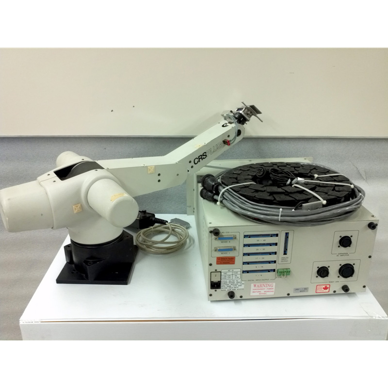
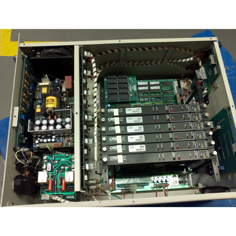
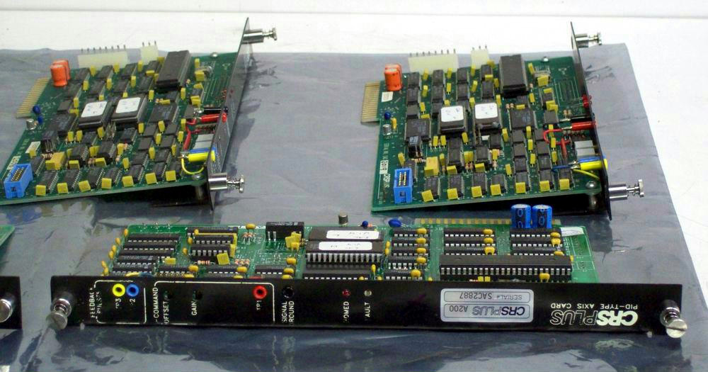
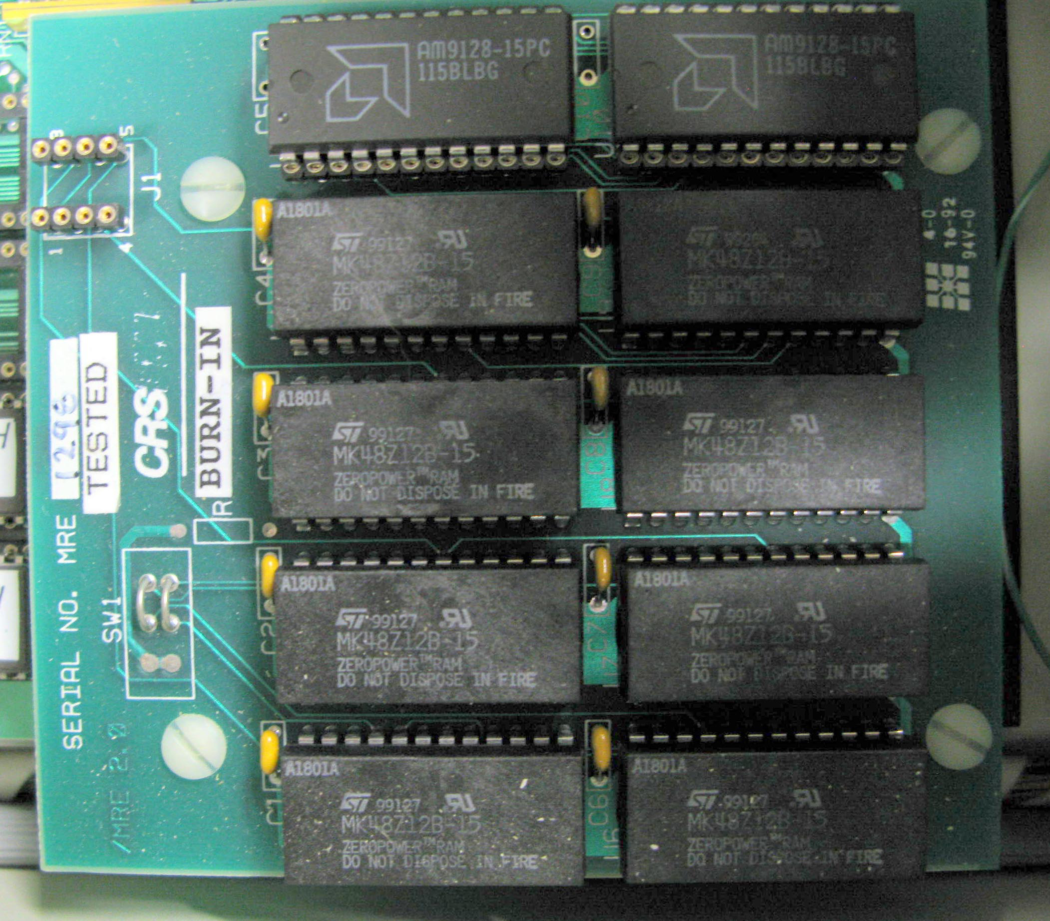
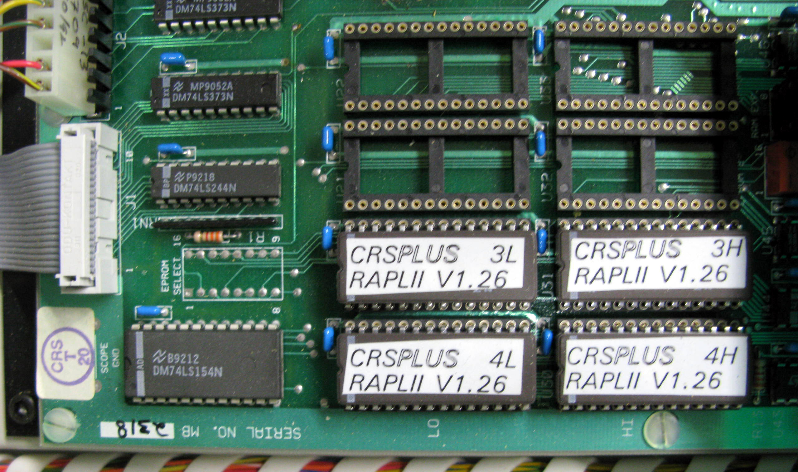
MODEL "A251" CONTROLLER & ROBOT
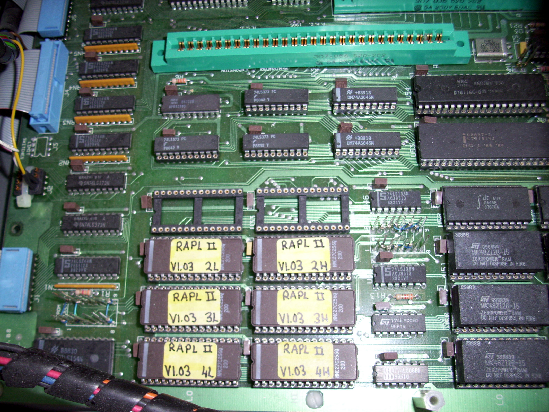
The controller MOTOR AXIS Driver Cards or (PID-TYPE AXIS CARDS) are very different in these upgraded controllers. Each AXIS Driver card has a Devoted INTEL P8095BH Micro-Controller to provide increased accuracy and responce time. Also shown above is the Motherboard RAM card as well as the RAPL II EEPROM memory Chips.
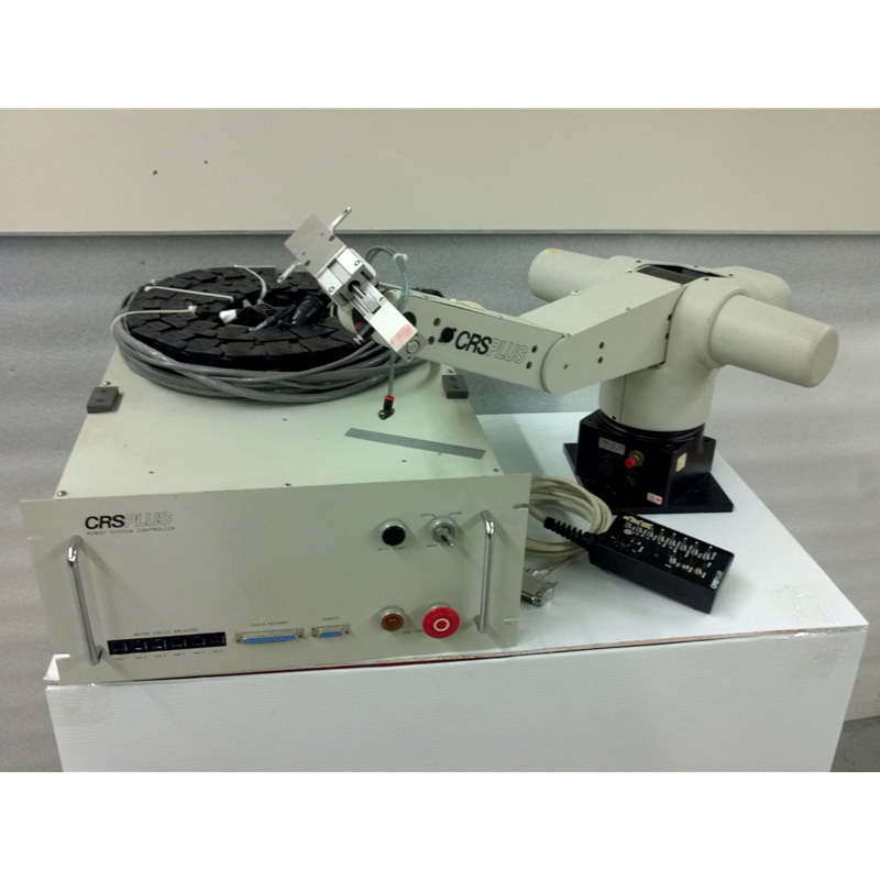
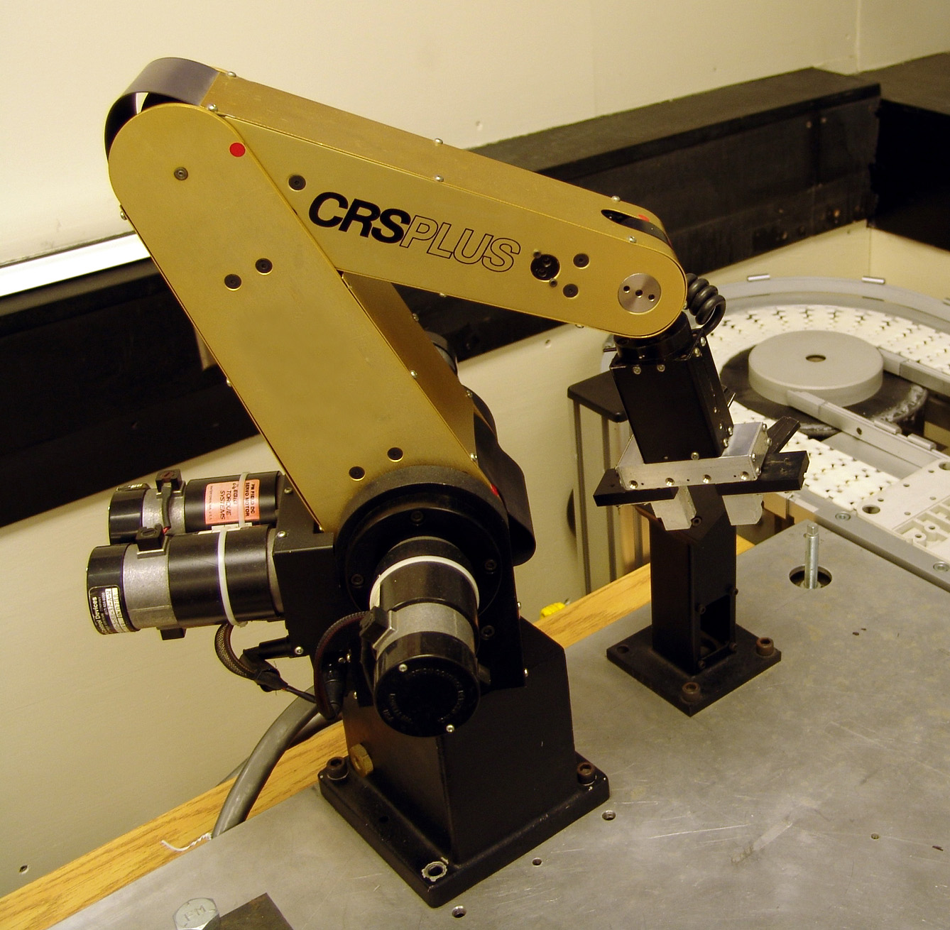
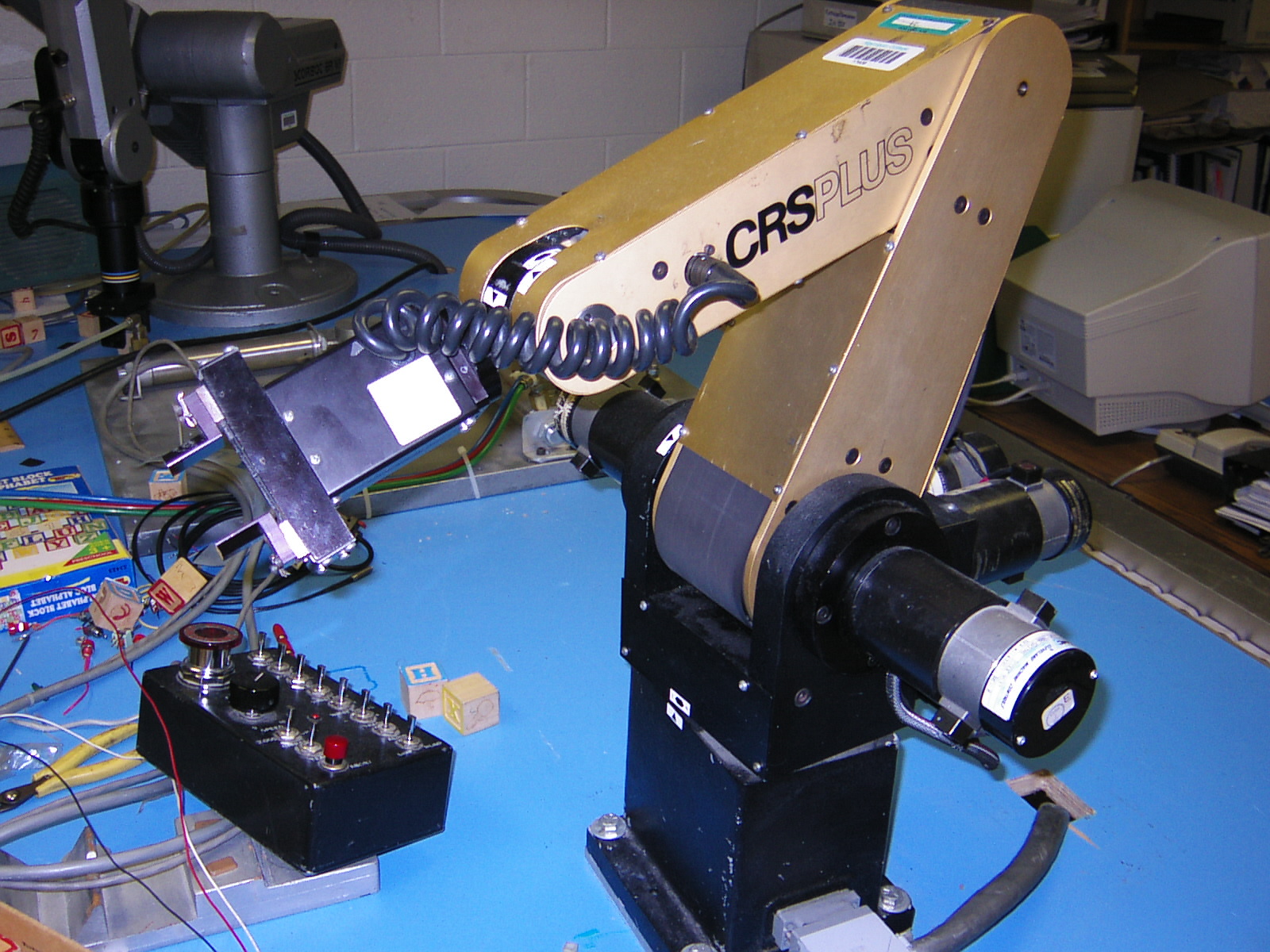
-= The CRS+Plus "SRS-M1A" Robotic Arm & Controller=- Shown below is a File photo of exact Model of Robot I used back in College. This is the CRSPLUS Model "SRS-M1A" robotic Arm unit. This system is paired with the "SRS-M1A" model robot Controller shown further below.
I have recently acquired a CRSPlus A250 robot from my good Friend Eric Mack. Eric is the Founder of the Scorbot Yahoo Group. http://tech.groups.yahoo.com/group/ScorbotUserGroup/ I also just recently aquired several manuals for this old system including a copy of the Contoller Software "ROBCOMM-II" that uses the RAPL-II programming language. I am using the manuals and the wiring diagrams they contain to Modify my A250 robot in oder to interface it with an SRS-M1A Controller using an EDAC connector. (Use the Links at the TOP of this page to view my "CRS-A250" model Robot)
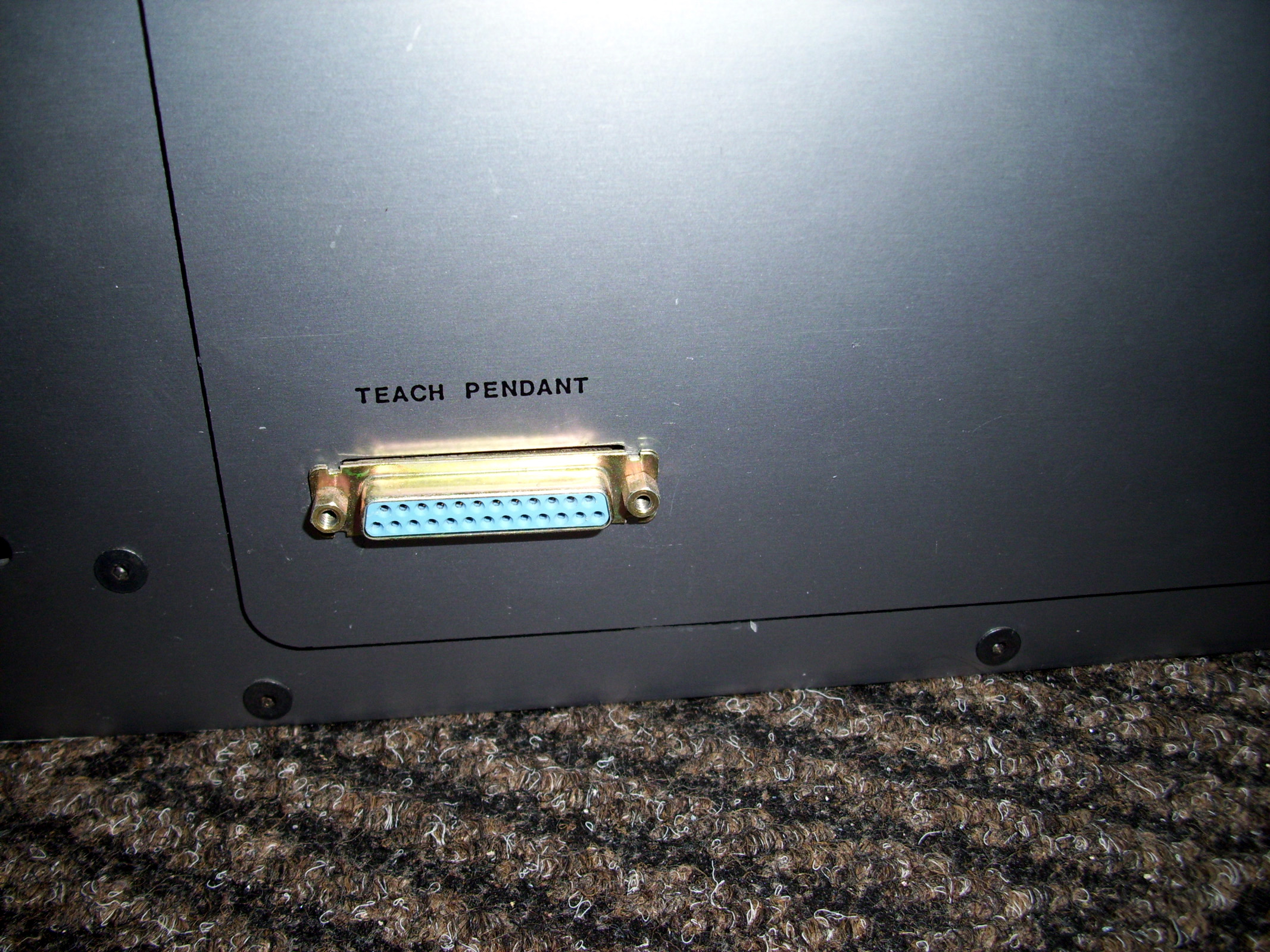
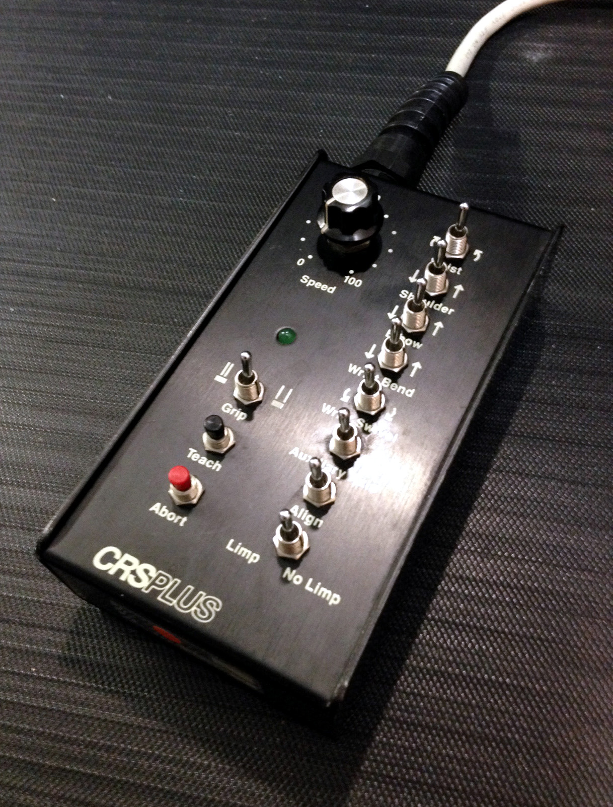
The Photo above was taken in the Robotics Lab durring my College Robotics program. This is the SRS-M1A Robot. Notice the "Teach Pendant" hand control sitting on the table next to the Robot arm for this system. This TP is actually designed with simple direct wiring between the cable and the various Toggle switches and speed control POT. Makes it an easy build for those that want to make their own CRSPLUS Teach Pendant hand controller. The Technical Manuals I post further below have the schematics for this Remote interface in case any of you wanted to try and build your own TP.
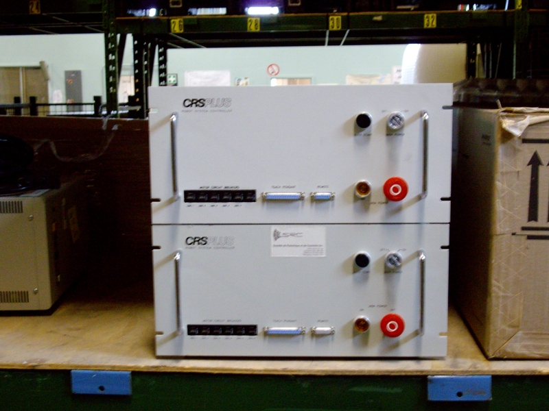
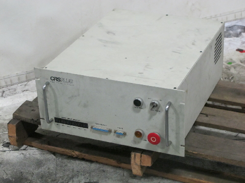
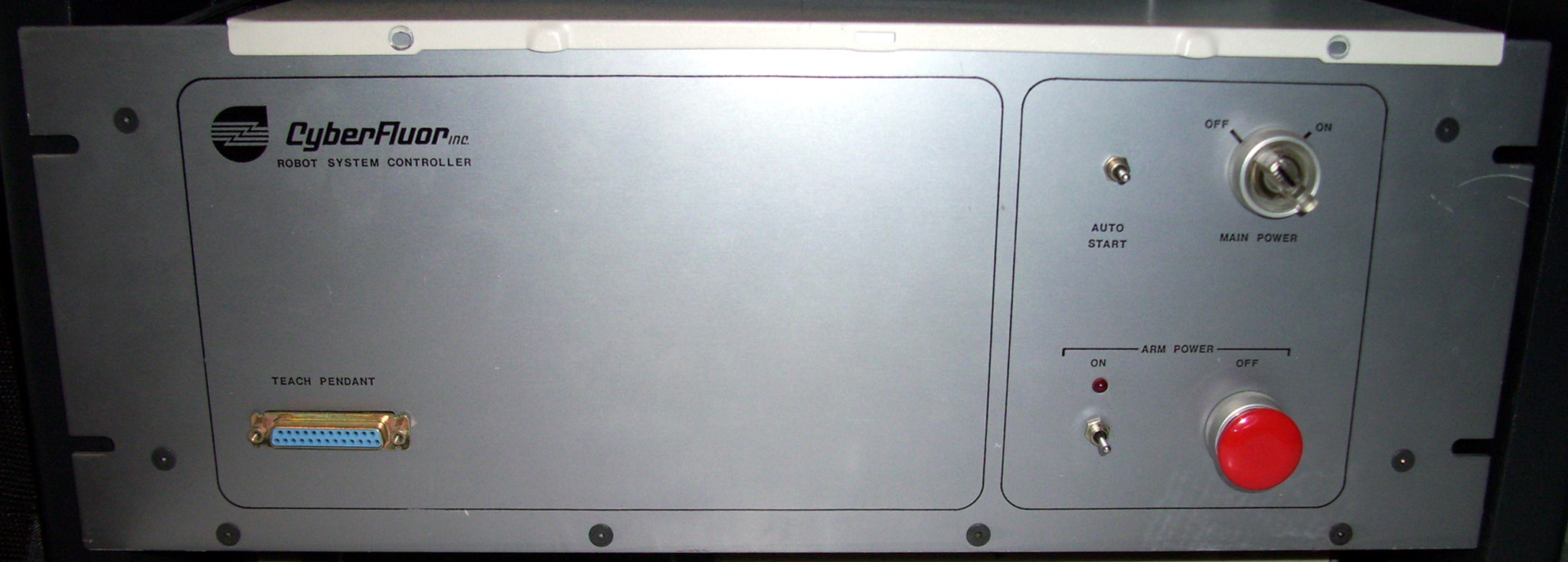
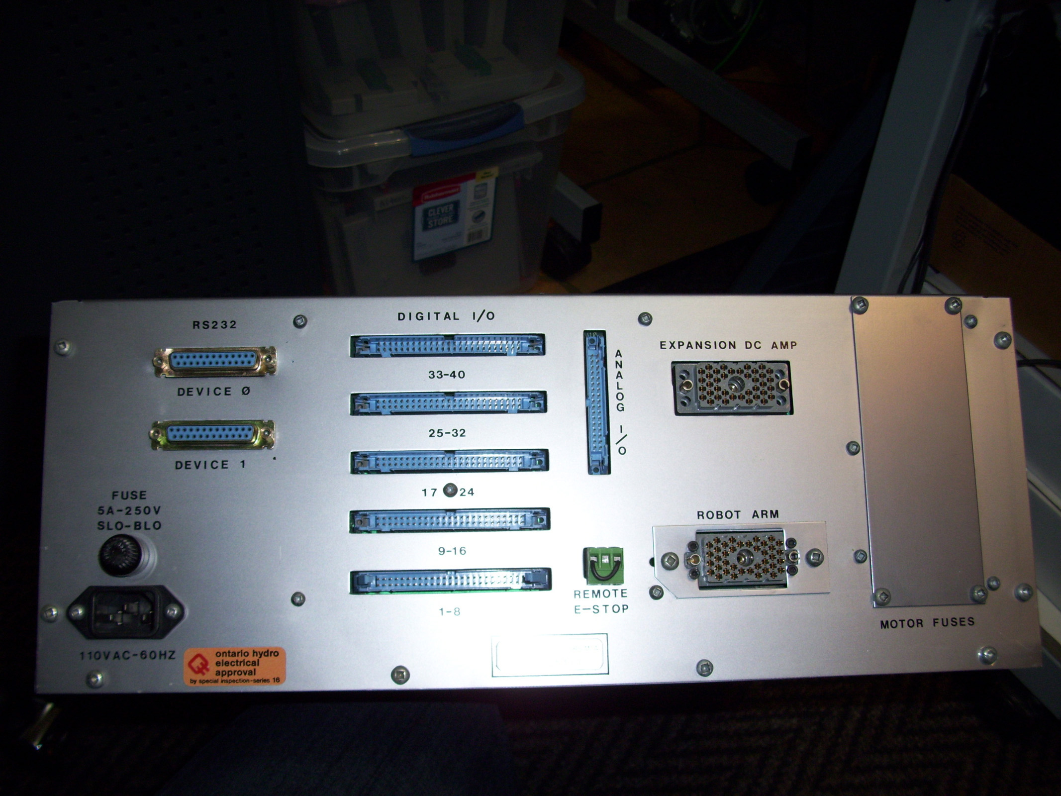
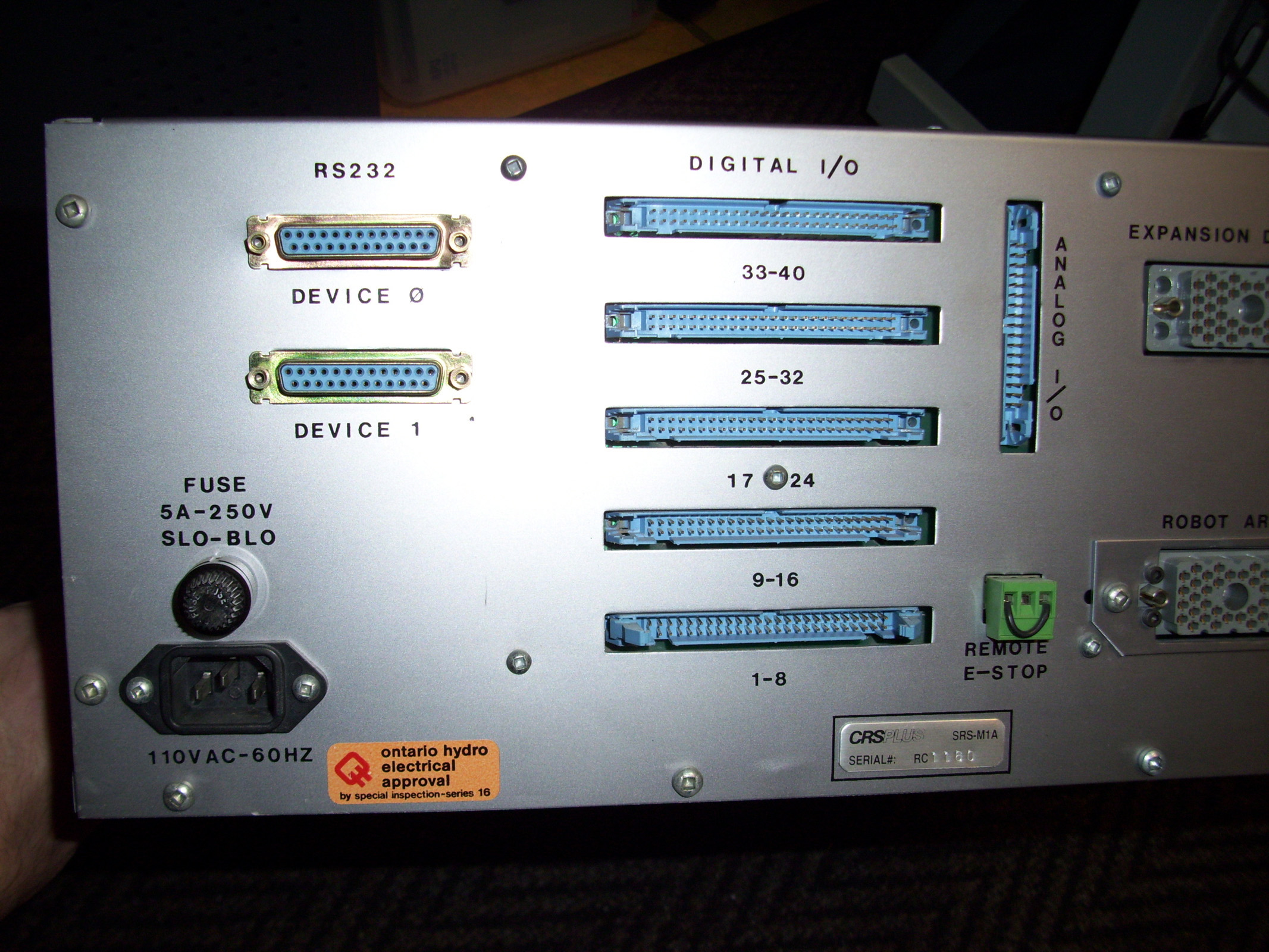
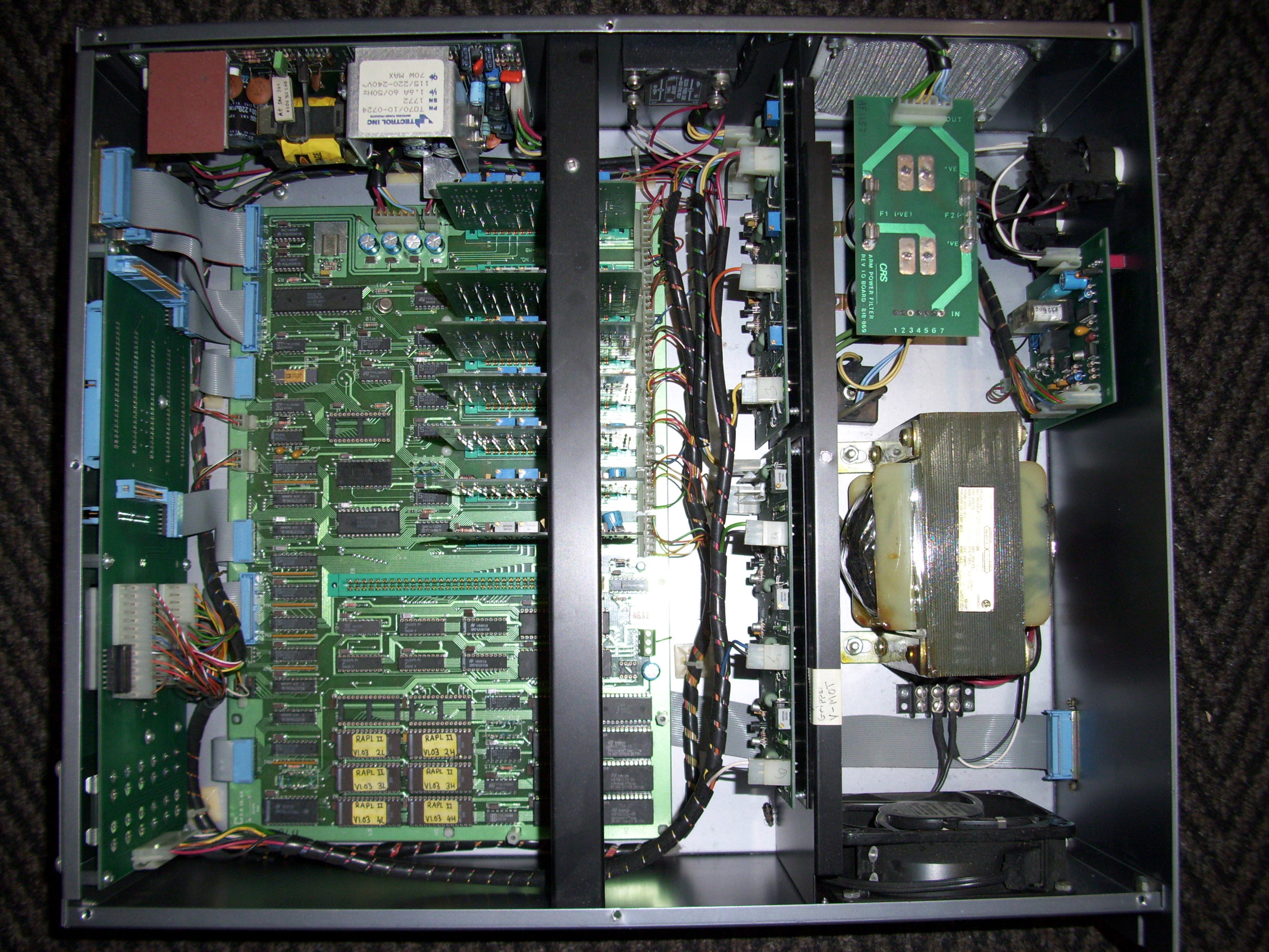
-= The CRSPLUS Robot Arm controller - Model "SRS-M1A" =- This is my SRS-M1A controller that I purcashed off ebay about 10 years ago, and I have been looking for a matching CRSPLUS "M1A" model robot arm to match up with it. I eventually gave up and decided to try and modify an A150 or A250 CRSPLUS robot to interface with it instead.
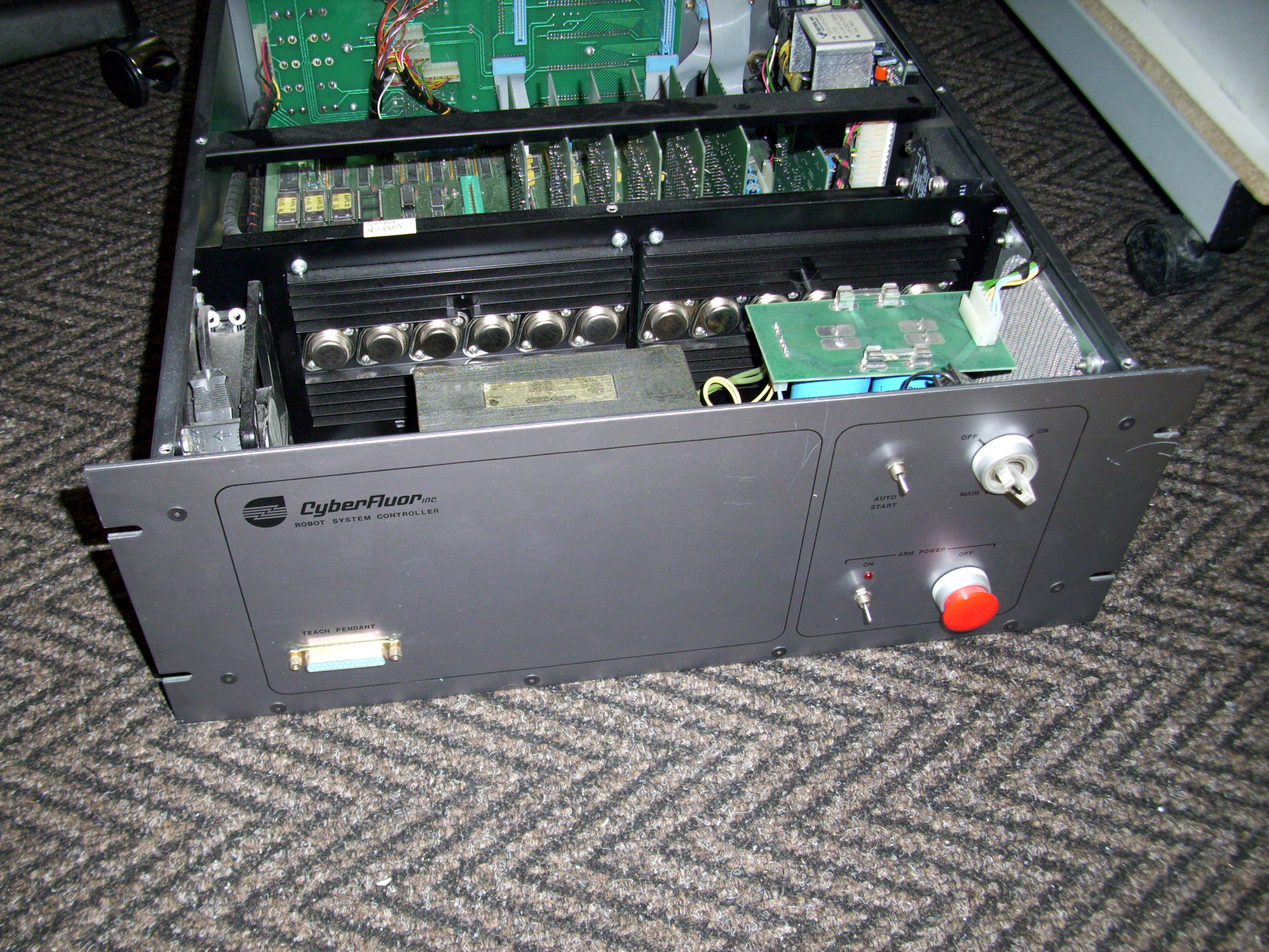
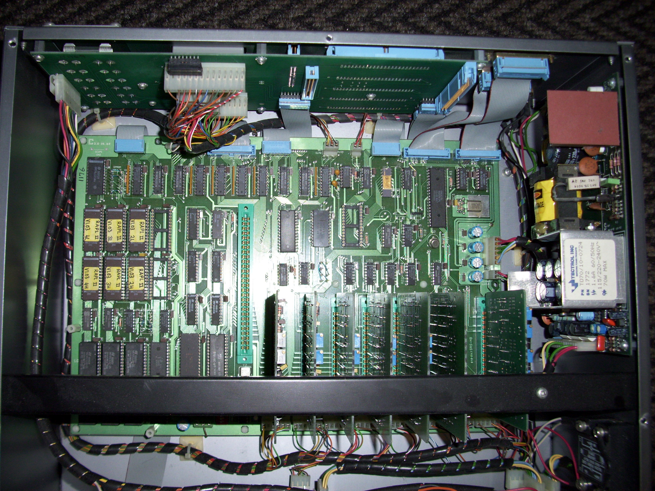
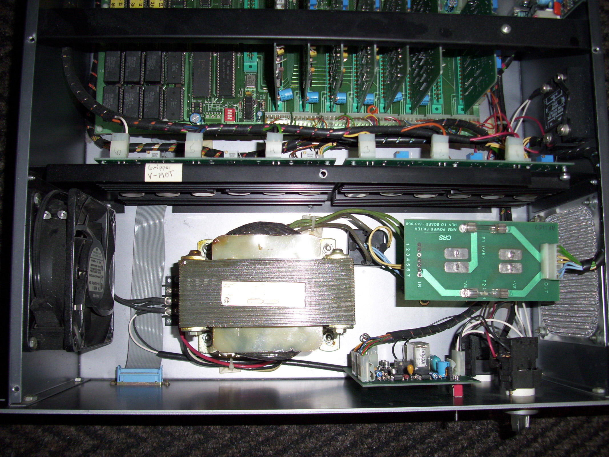
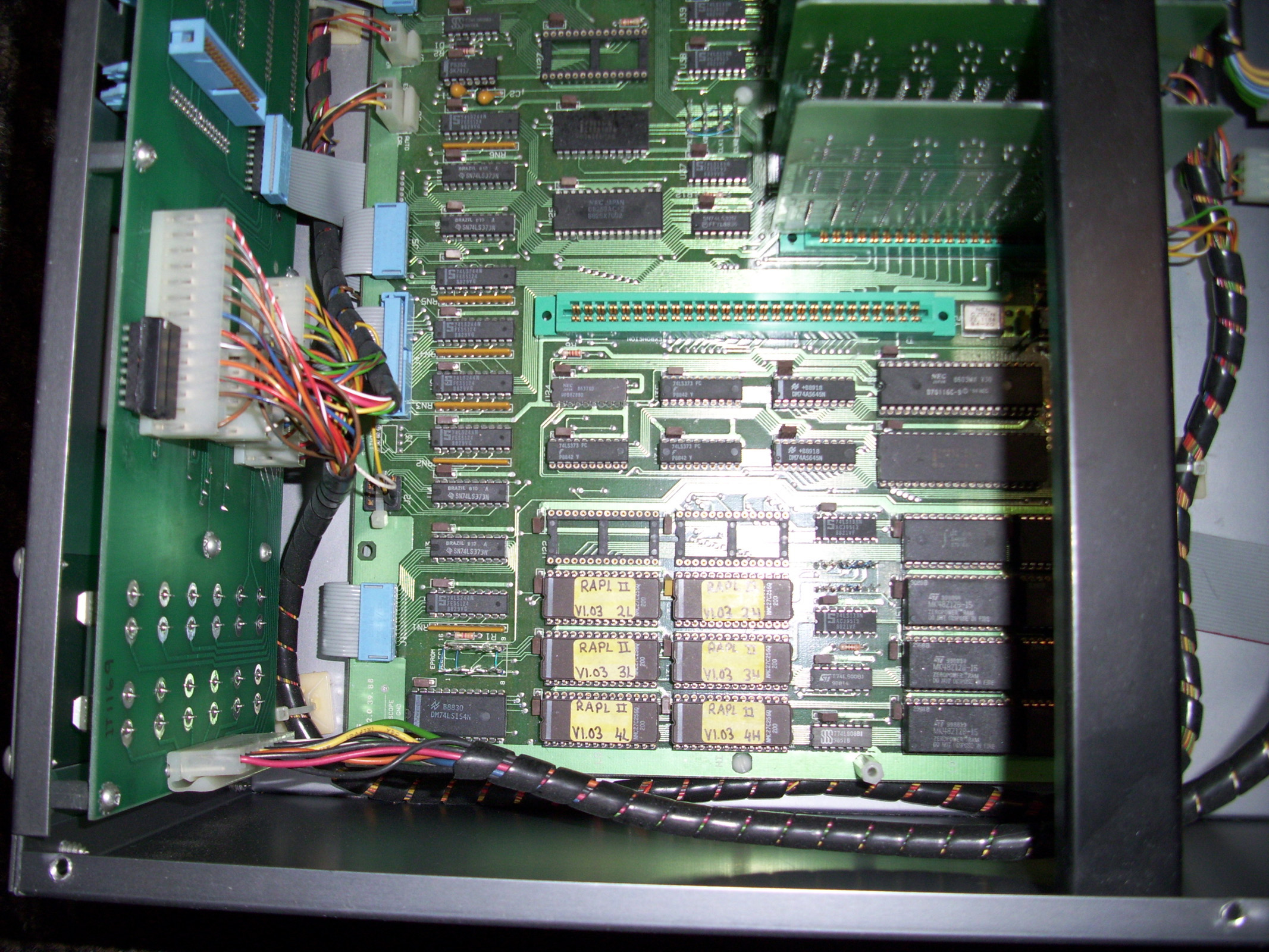
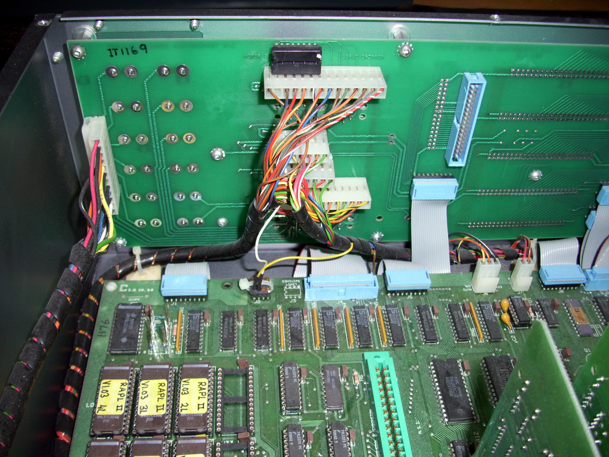
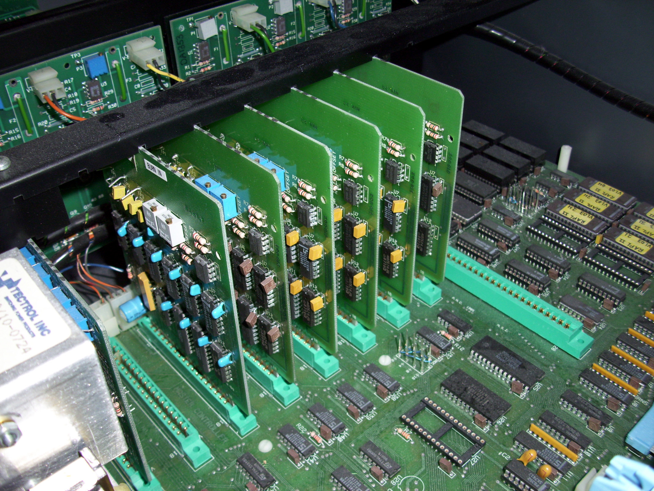
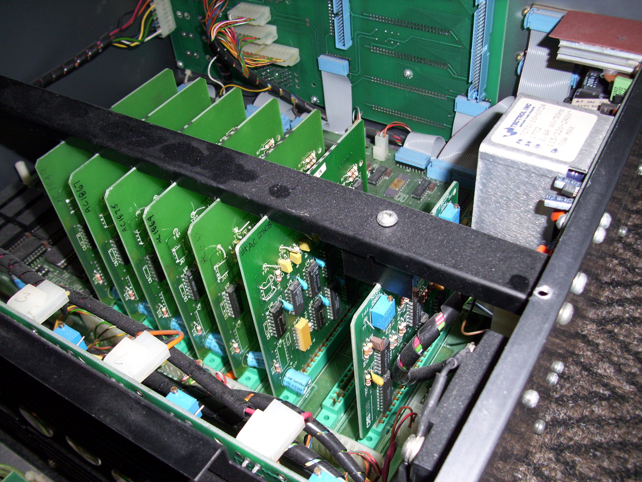
-= The SRS-M1A controller - Motor Driver Cards =- The SRS-M1A controller has 2 different types of Motor Driver cards within its system. The first is the Servo Axis Driver card, used for all the Robot Arm Axis Motors. The second is the Gripper motor Driver card, and of course this is used for the Robot Servo Gripper. There are 8 slots on the Motherboard and Slots 1-7 are for the Robot arm Axis Cards. Slot #8 is devoted to the Gripper Driver Card.
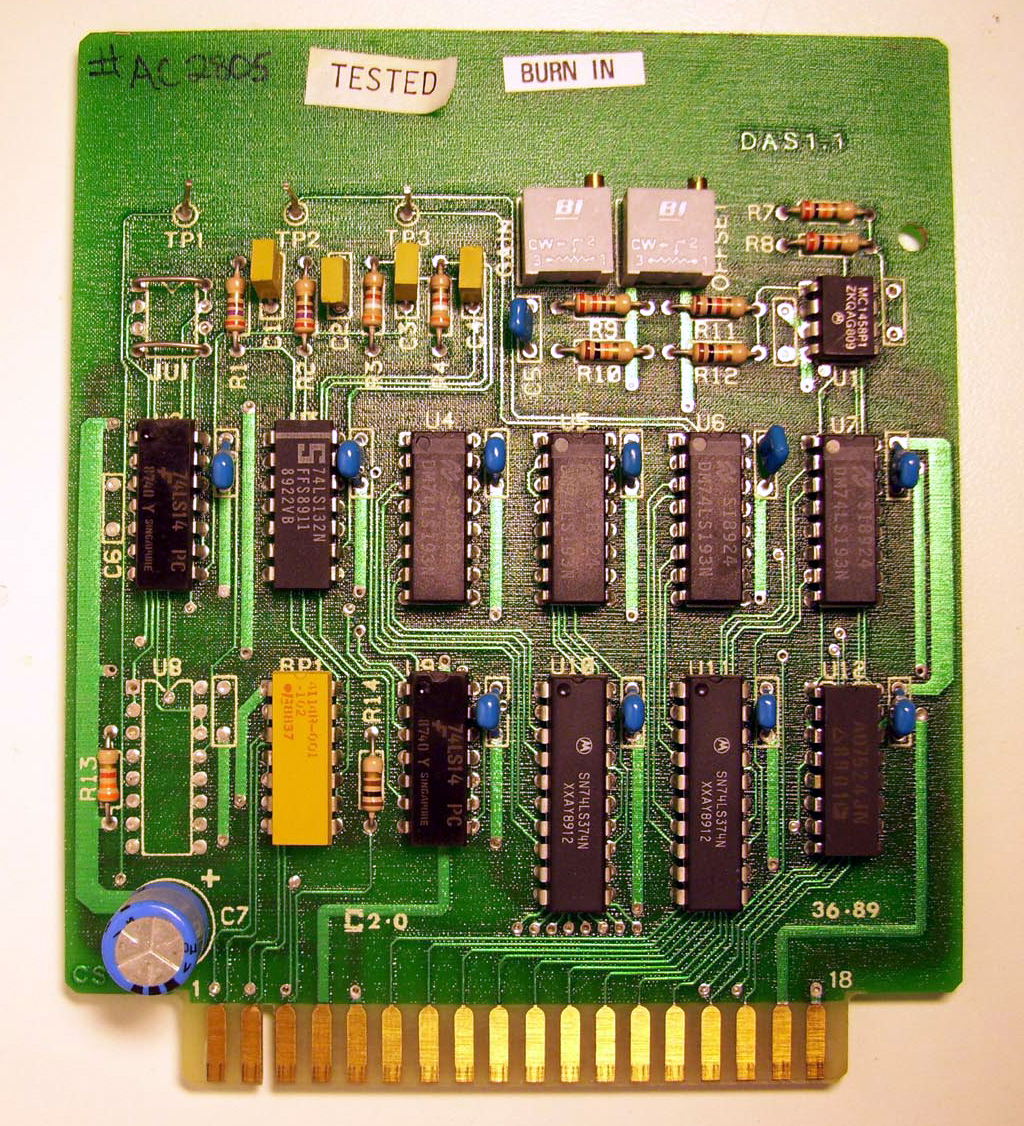
As you can see in the pictures above, the Gripper Driver Card (TOP RIGHT IMAGE ABOVE) has 5 Trimmer-POTs which are used for calibration settings. The Motor Axis Driver cards only have 2 Trimmer-POTs. As seen in the schematic diagrams above, the Trimmer-POTs calibrate Gain, Offset and Position feedback levels for the various Motor Drive circuits.
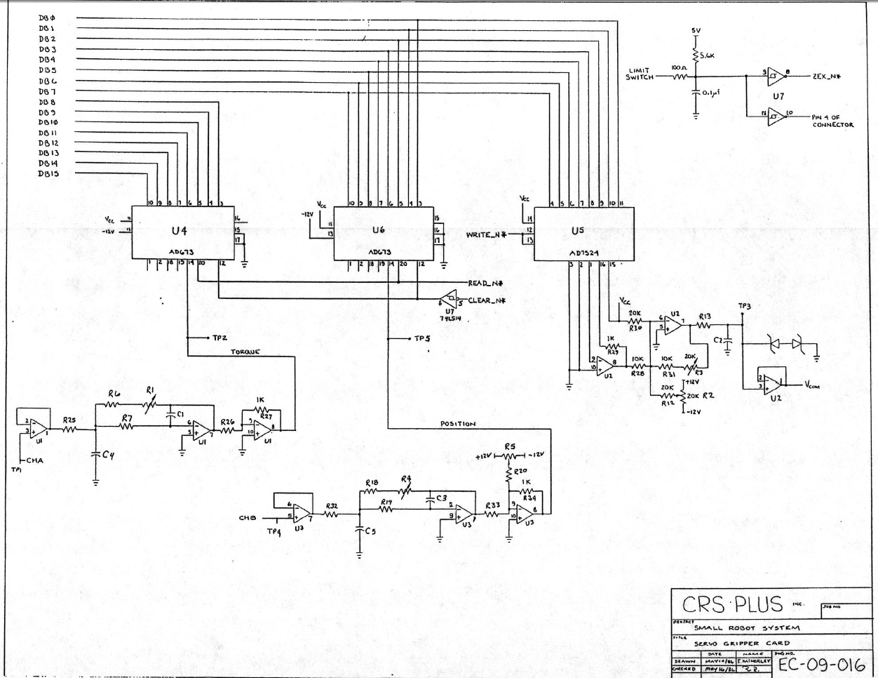
-= Servo Gripper Card Calibration=-
(Use the Gripper card Schematic diagram shown further above as reference.) -= Gripper Torque CIRCUIT - TEST POINTS #1 & #2 - USE Trimmer POT R1 =- Test Points 1 & 2 are for the Motor "TORQUE" feedback circuits. Test Point #1 is the TORQUE feedback signal originating from the Gripper Motor and this is the INPUT signal to the TORQUE control Circuit. Test Point #2 is the output signal of this Analog TORQUE control Circuit and is fed into PIN#14 of the AD673 Analog to Digital Converter Chip. This analog signal is converted into a Digital 8-Bit DATA Bus and is read by the Controller for monitoring. Use Trimmer-POT "R1" to adjust the "TORQUE" circuit Gain levels.
-= Analog Command Voltage CIRCUIT - TEST POINT #3 - Use Trimmer POTs R2 & R3 =- Test Point #3 is the Analog Command OUTPUT Voltage. The Source of this Analog Voltage originates from "U5" an AD7524 chip (DIGITAL to ANALOG CONVERTER). This voltage is then filtered by a series of OPAMP filter circuits involving U1 and U2 (LM324N Quad-OPAMP IC) and Trimmer-POTs R2 & R3. The final filtered output voltage is our VCOM voltage and TEST Point #3 Which is also being monitored by the main Controller processor. This should be in the Range of +- 10 Volts DC and will fluctuate in this range based on the Gripper being in the OPEN or CLOSED state. This Analog OUTPUT Voltage level (A.K.A. Analog Command Voltage or VCOM) is determined by an 8-Bit DATABUS signal sent from the Controller to the AD7524 Digital to Analog Converter Chip on the Gripper Driver card. Trimmer-POTs R2 & R3 adjust the Analog OUTPUT Voltage by varying its "Offset" and "Gain" signals accordingly.
-= Gripper Position Feedback CIRCUIT - TEST POINTS #4 & #5 - USE Trimmer POTs R4 & R5 =- Test Points 4 & 5 are for the Gripper Motor "POSITION" feedback circuits. Test Point #4 is the Position Feedback signal originating from the Center TAP of the 10Kohm Potentiometer in the Robot Gripper. This is essentially the Input signal to the Position Feedback Circuit. Test Point #5 is obviously the circuits OUTPUT signal. THis Output signal is Fed into PIN#14 of the AD673 Analog to Digital Converter Chip. The AD673 ADC chip, converts this Analog voltage into a Digital 8-Bit DATABUS. This DATABUS is monitored by the Controller and is essentially an 8-Bit digital representation of the Gripper Position. Use Trimmer-POTs R4 & R5 to Adjust the Position OFFSET & GAIN accordingly.
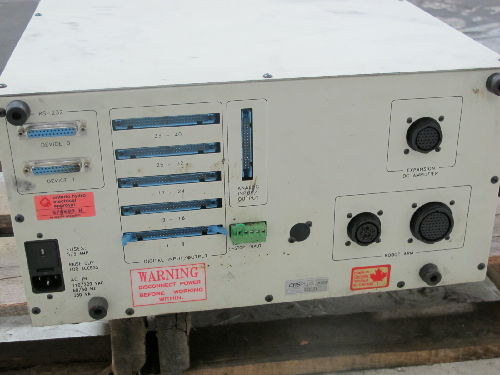
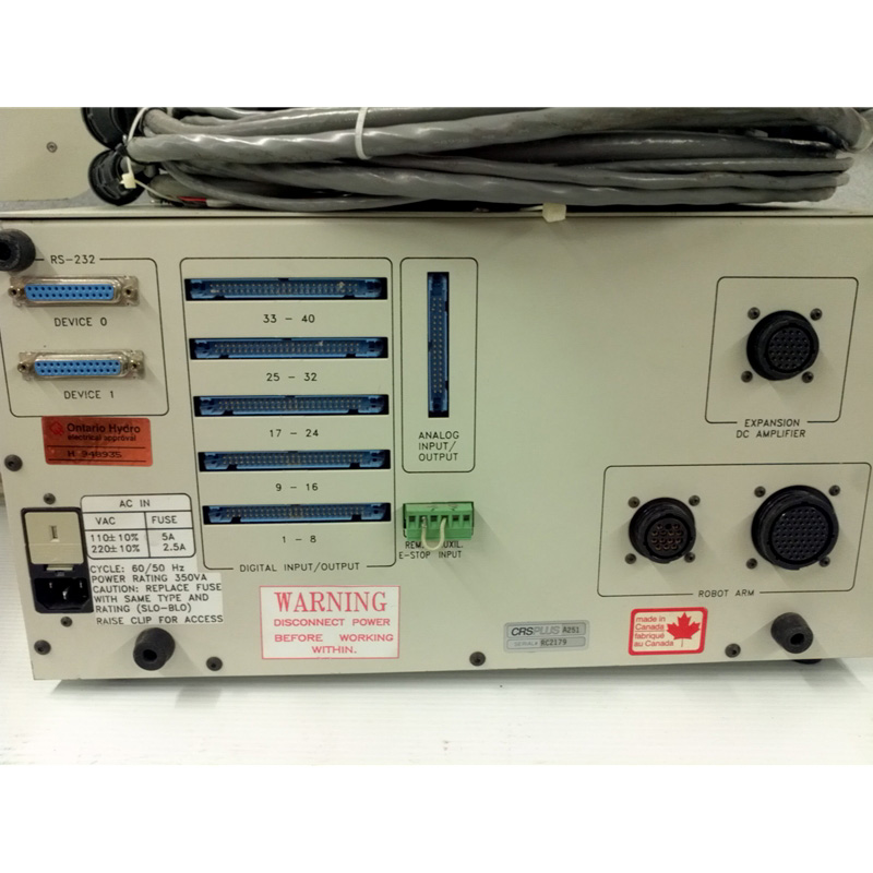
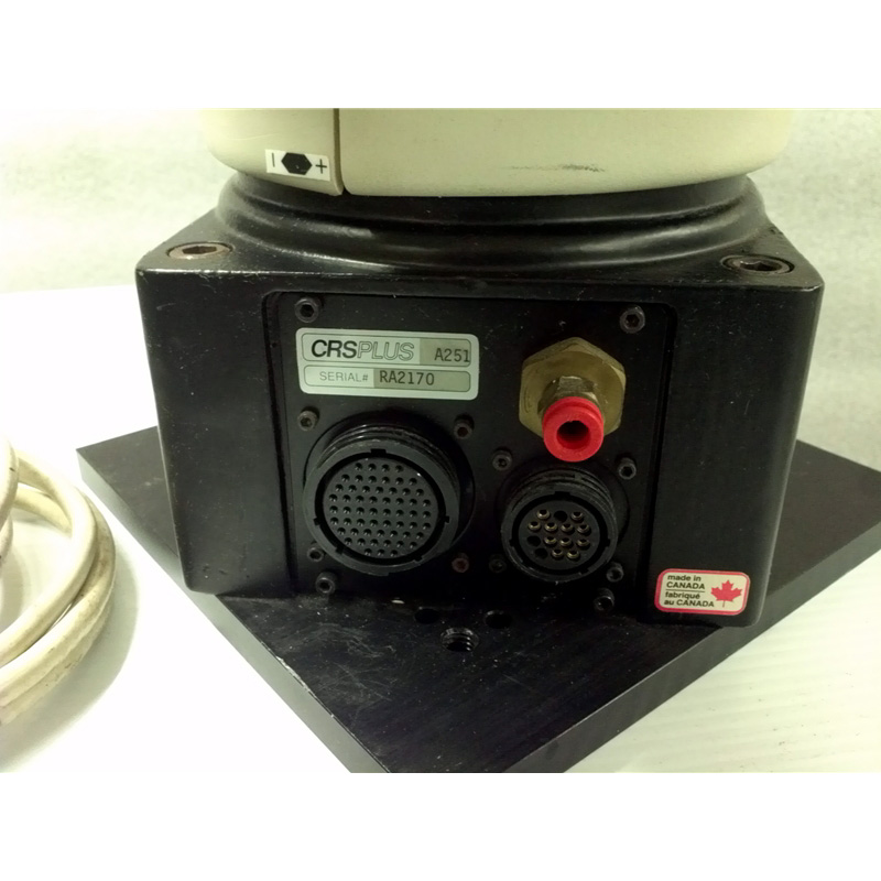
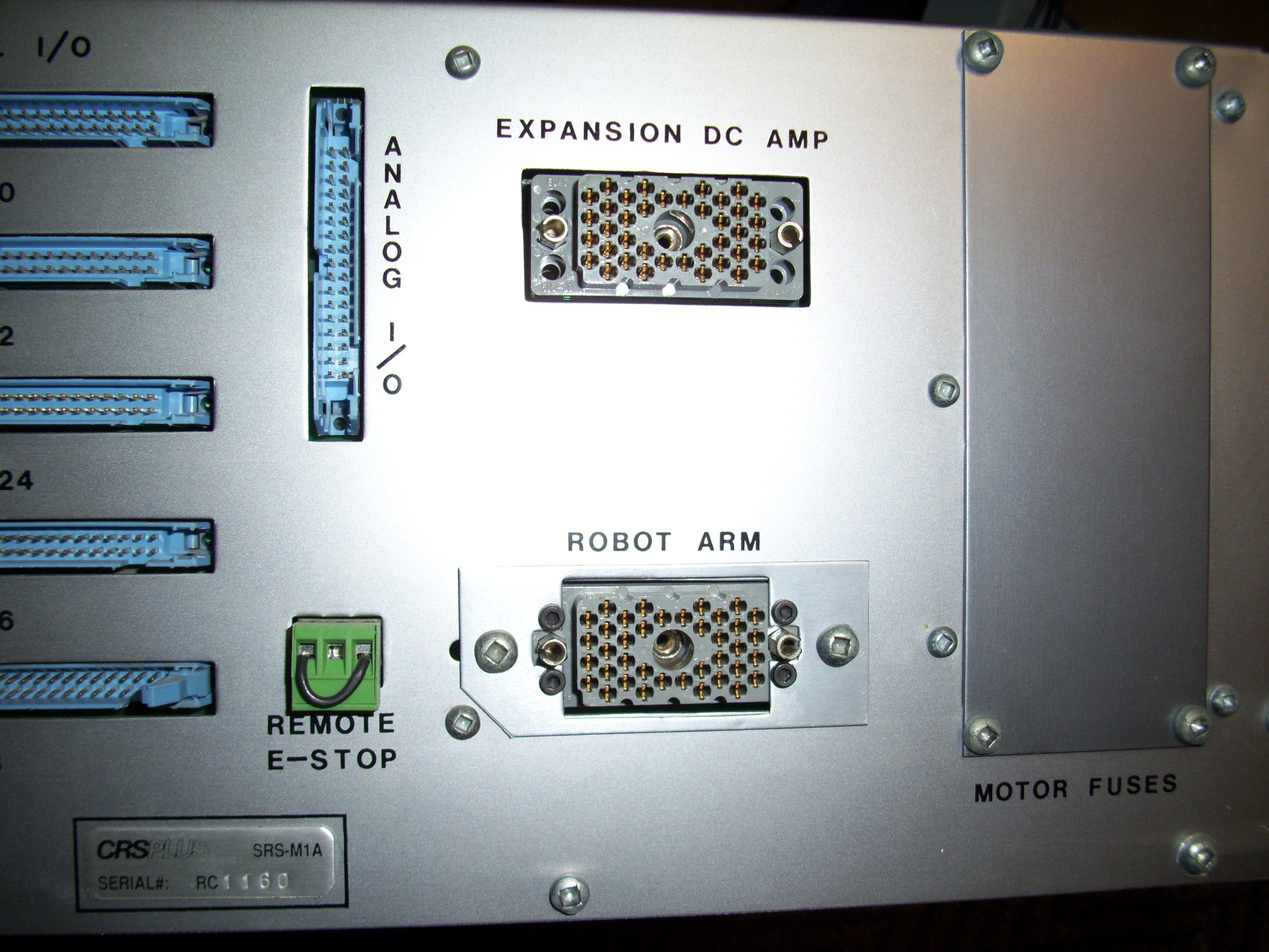
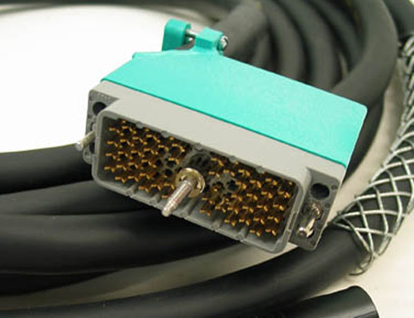
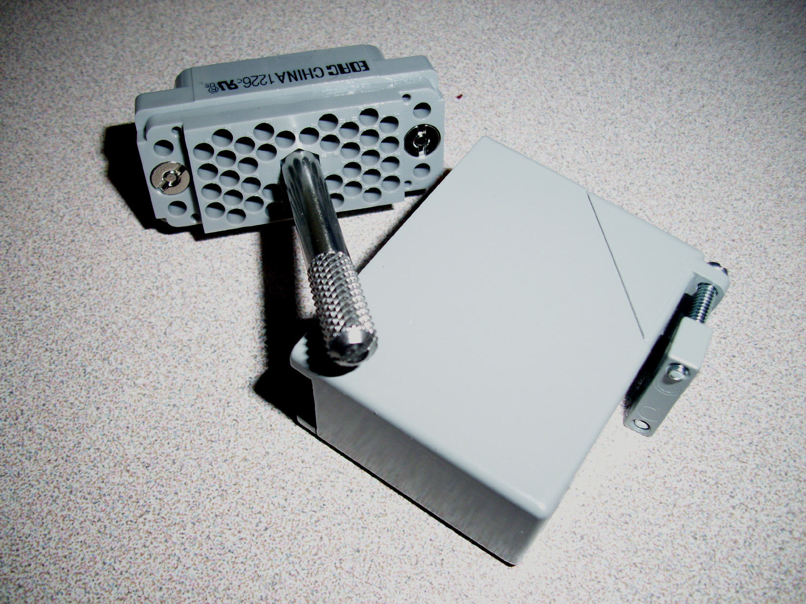
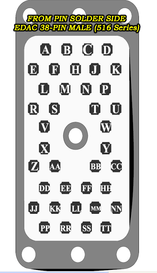
-= The SRS-M1A controller EDAC Connectors =- Shown Below are the "EDAC" Series 516 Connectors which are used with the CRSPlus Robots including the SRS-M1A controller.
EDAC SERIES 516 ORDERING DATASHEET: http://www.digital-circuitry.com/FILES/CRS_Robot/EDAC_SERIES_516_Connectors/EDAC_Series_516.pdf
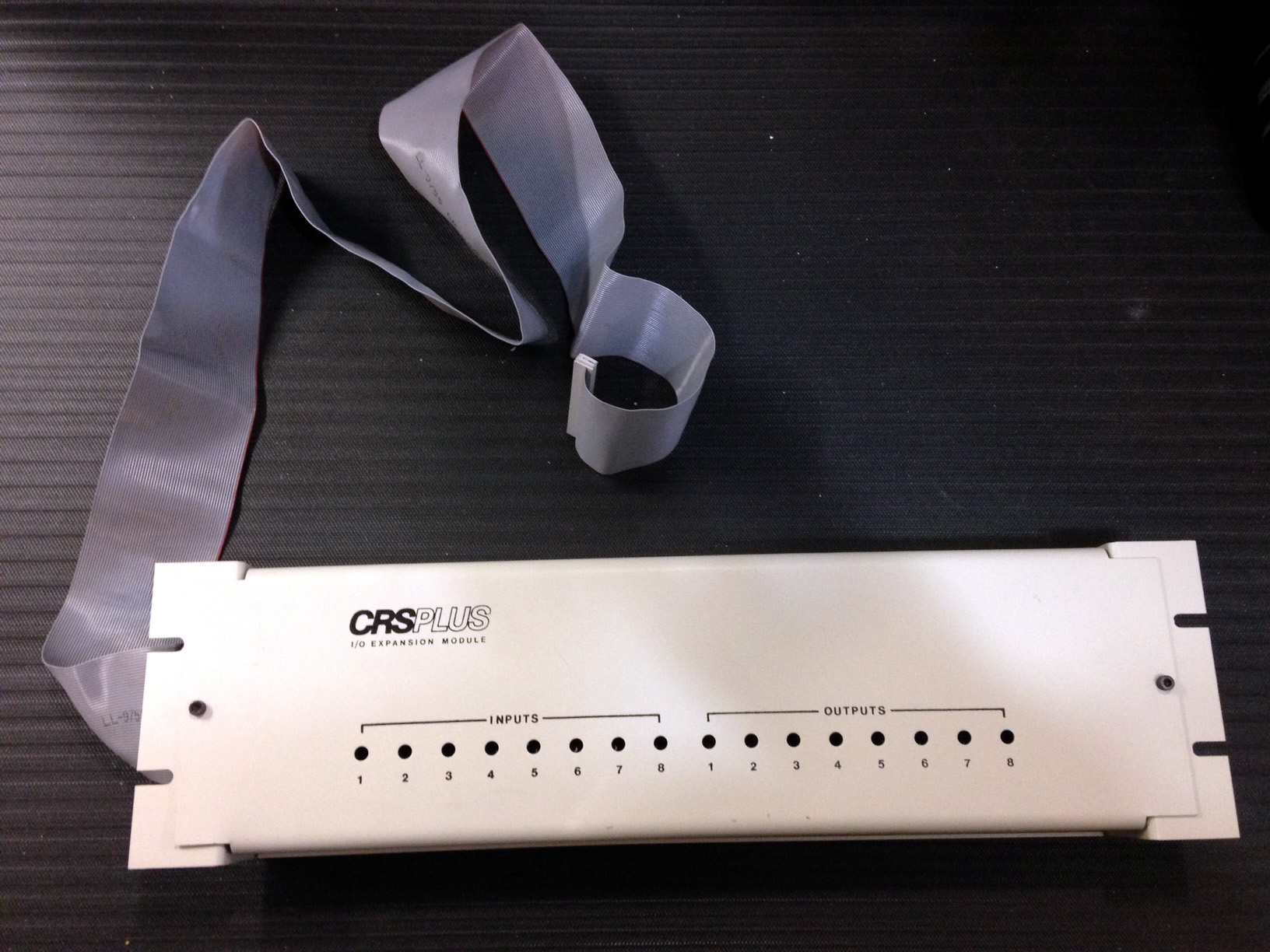
-= CRSPLUS Robot System Accessories =-
Shown above is the CRSPLUS Controller Teach Pendant accessory, along with the I/O Expansion Module.
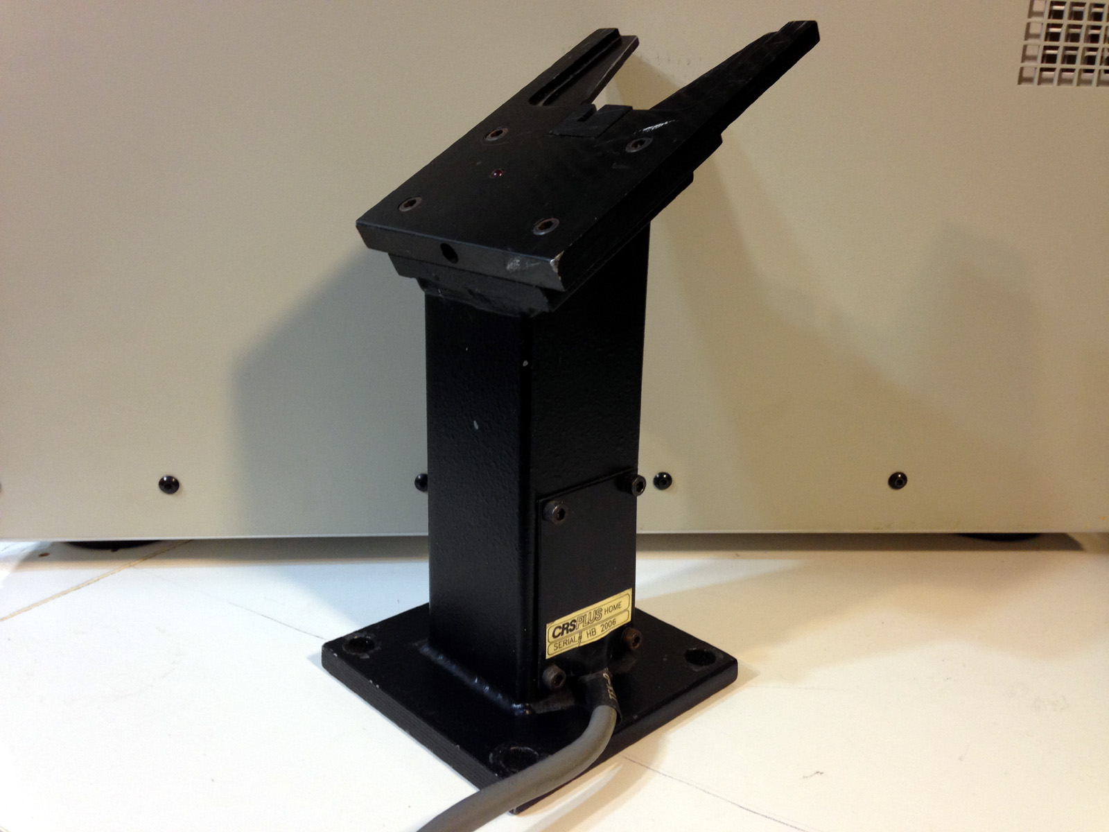
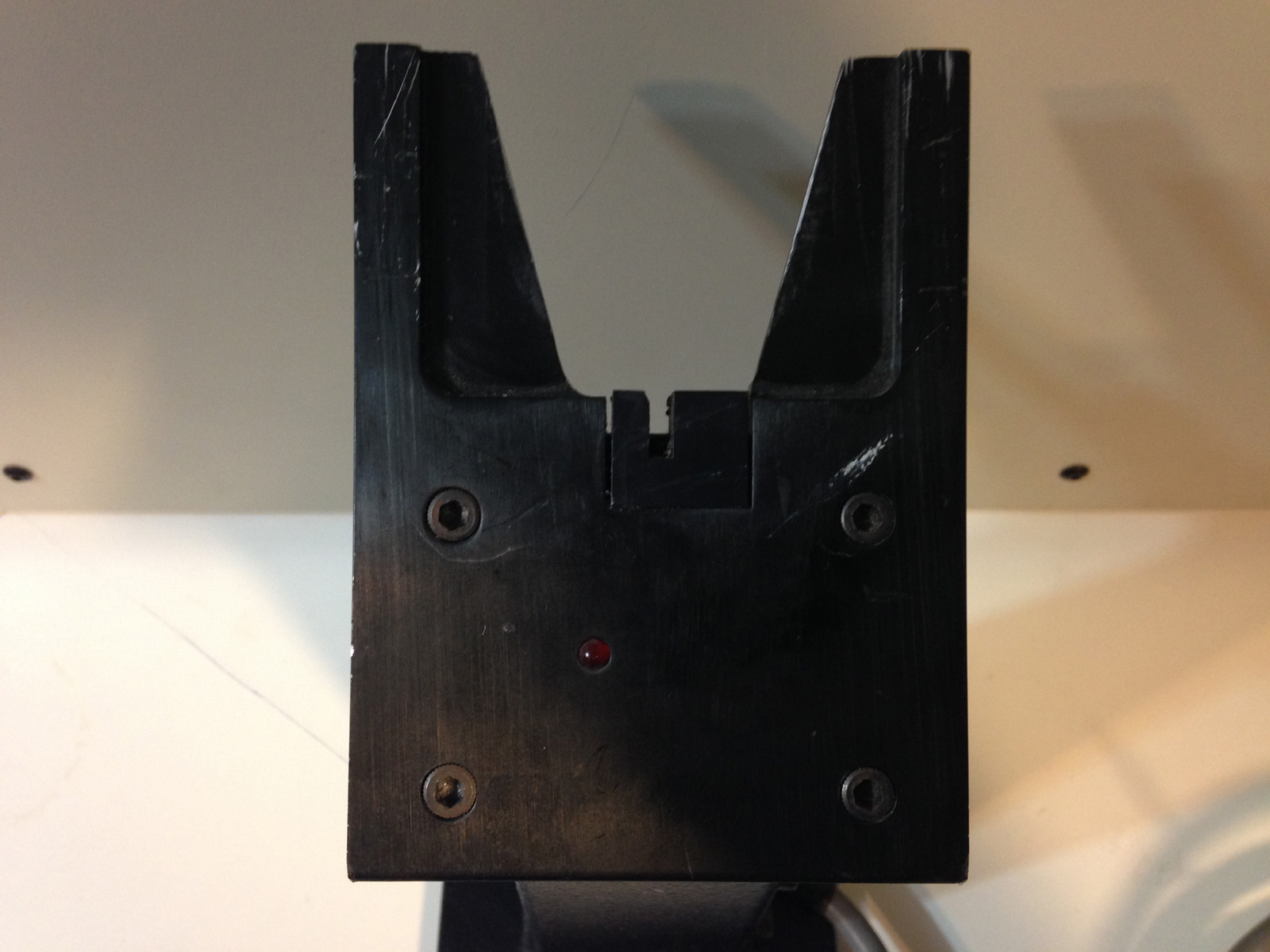
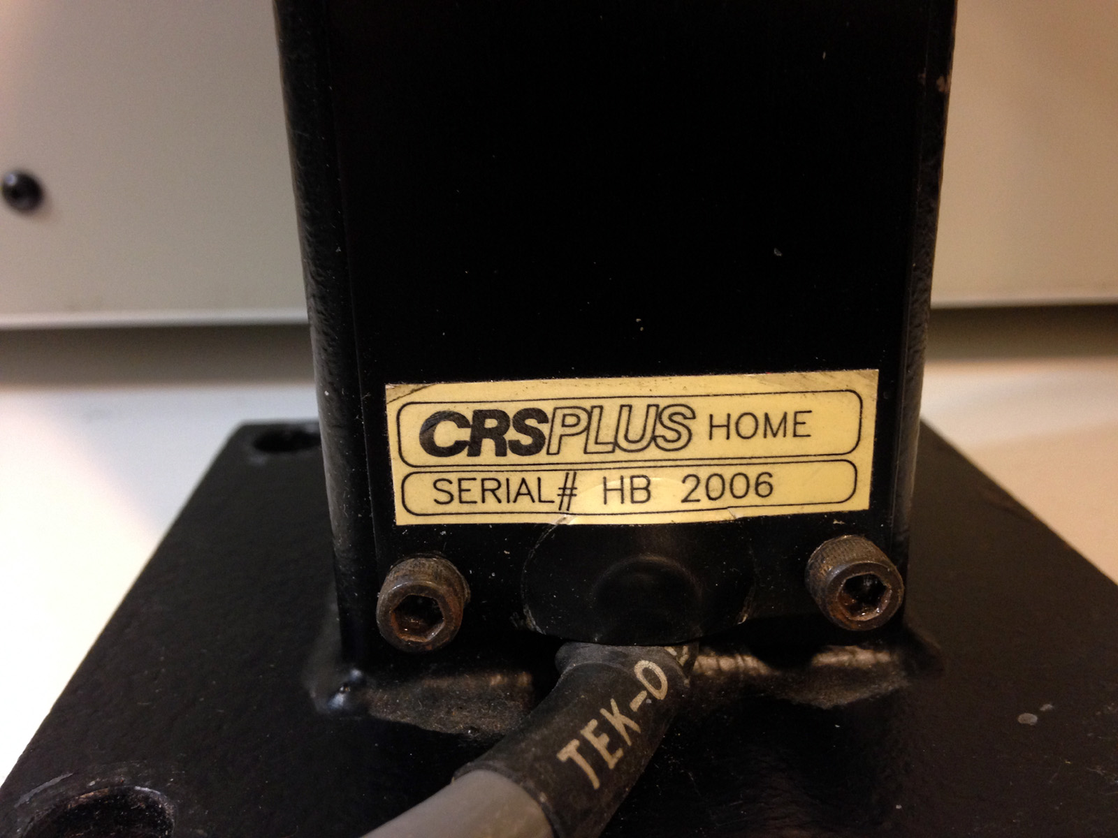
Shown above is the CRSPLUS Robot Arm "HOME" Homing Post. This steel mast houses an Infrared sensor for detecting when the Robot Gripper docks with the mast. This also supports the Arm when the system is turned off.
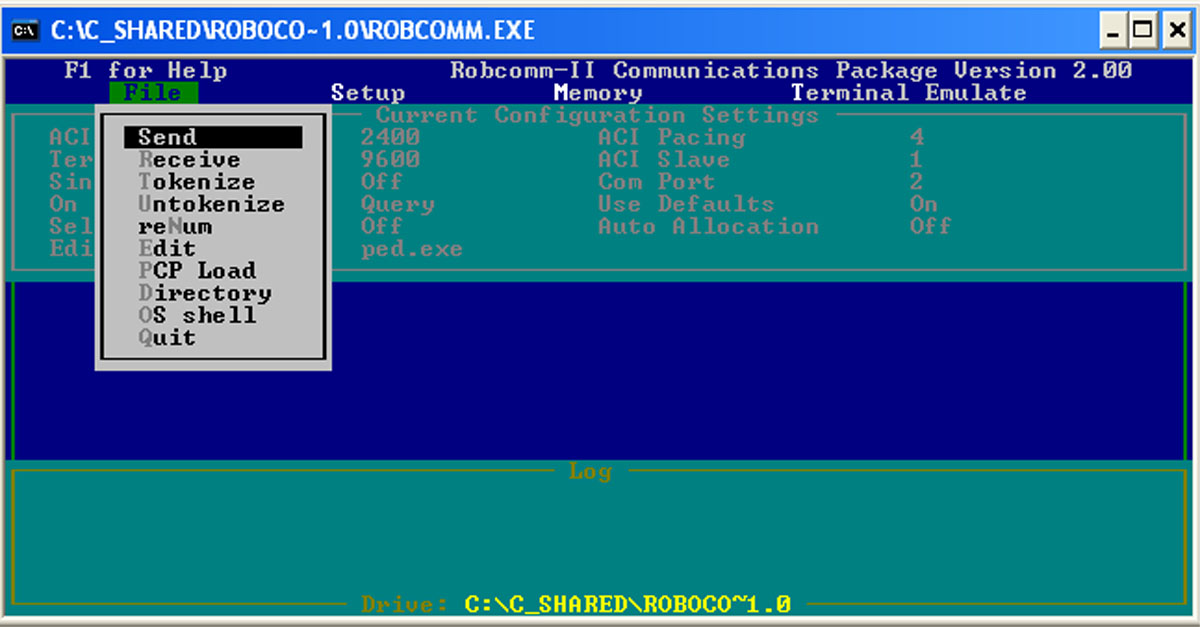
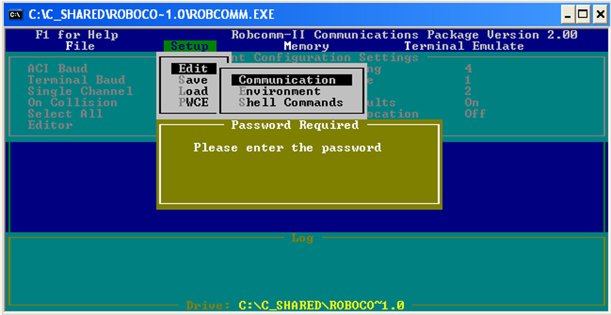
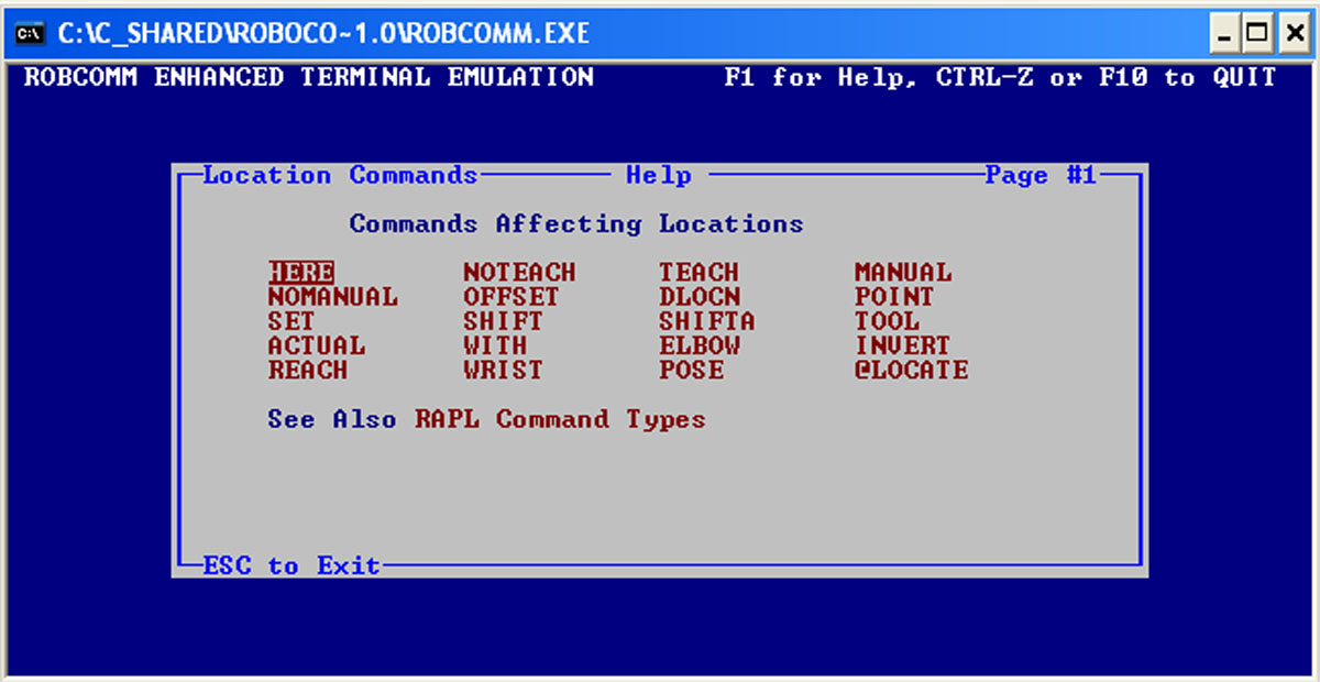
"CRSPLUS robot programming Software "ROBCOMM-II" The various CRS-PLUS controllers use a DOS programming software called "ROBCOMM-II" as shown below. The software language they use is referred to as "RAPL".
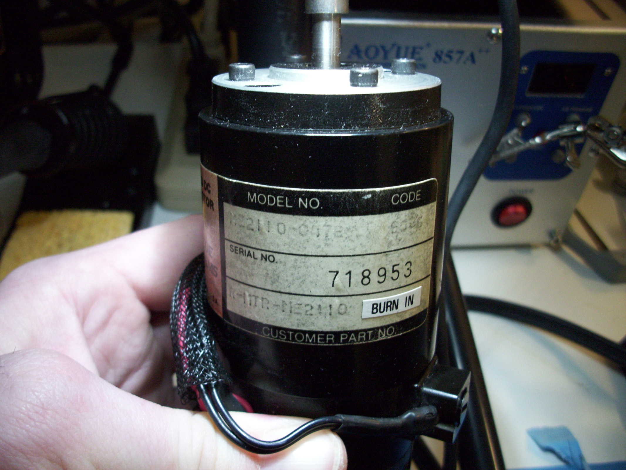
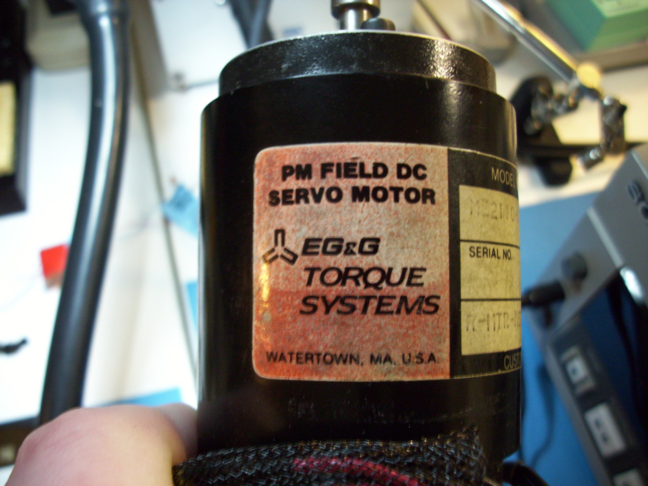
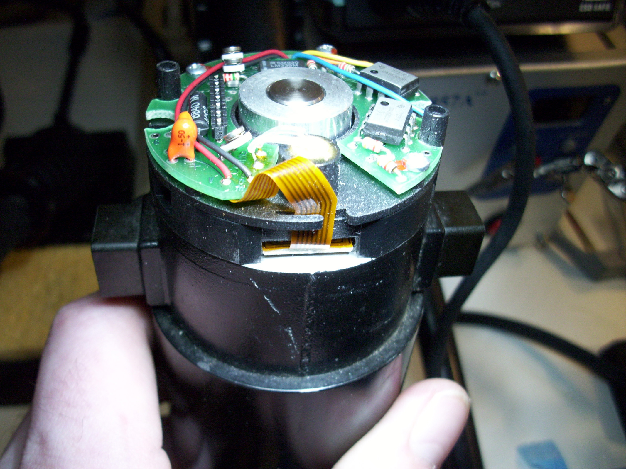
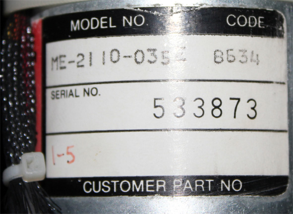
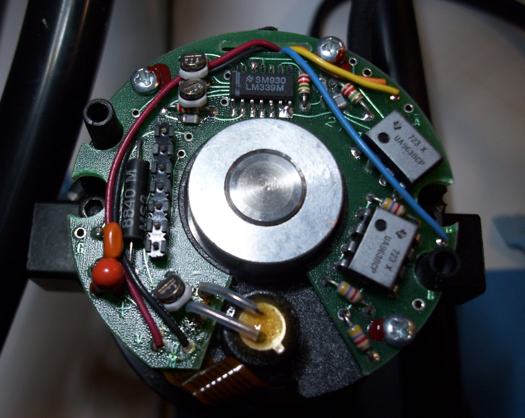
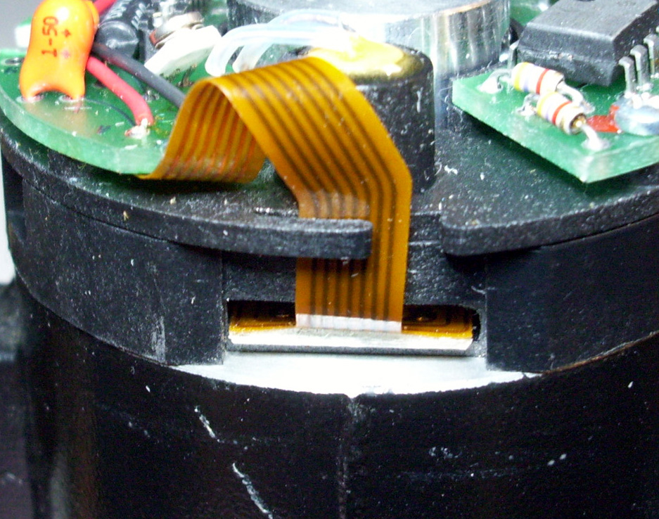
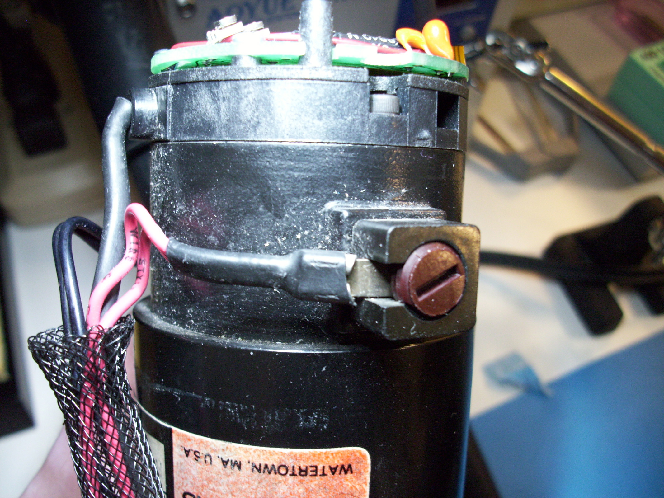
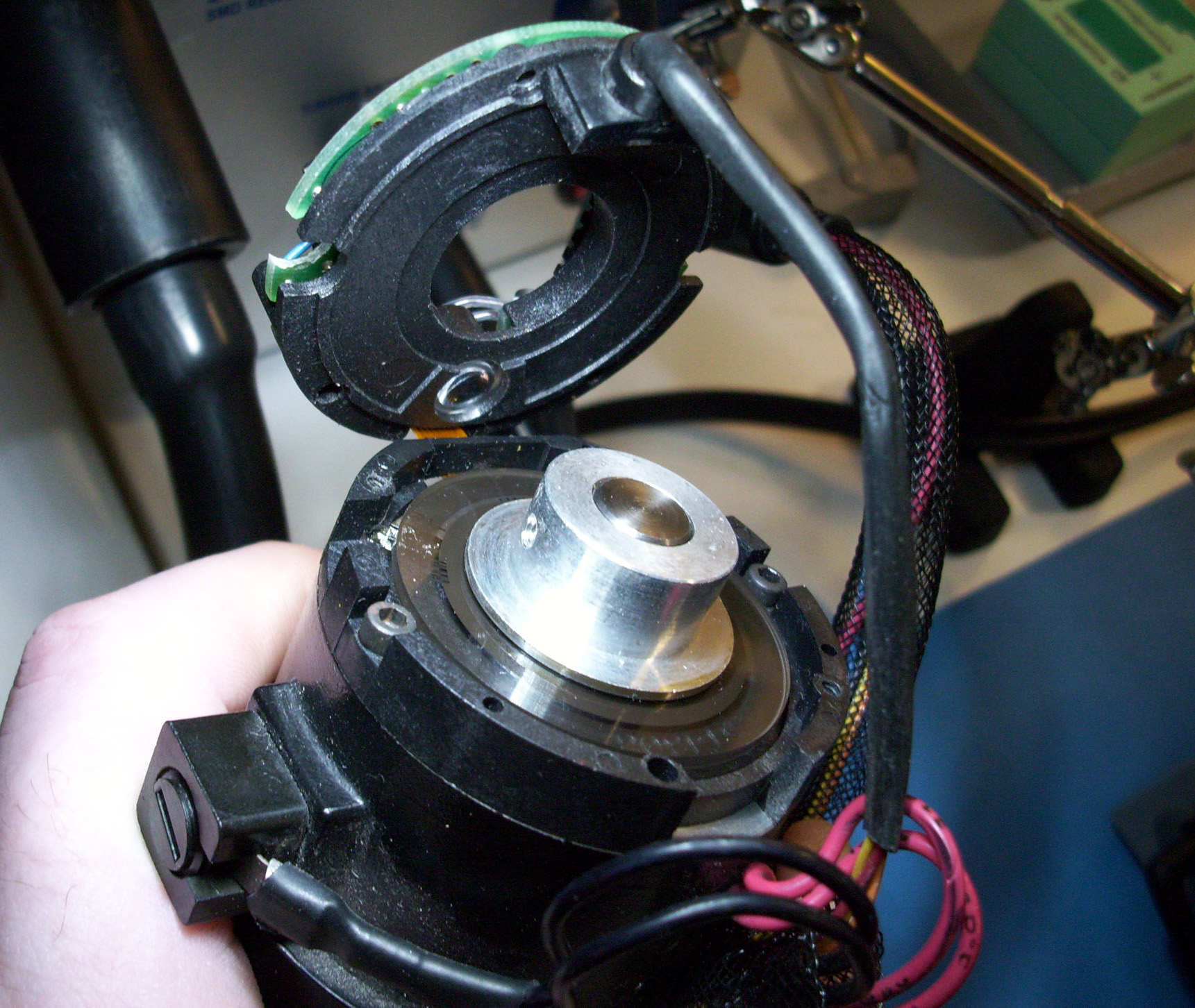
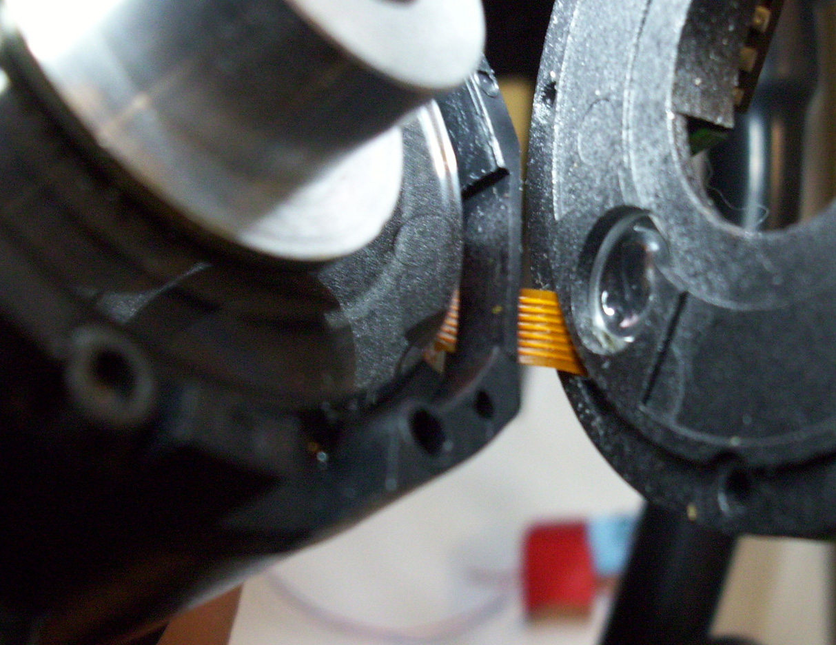
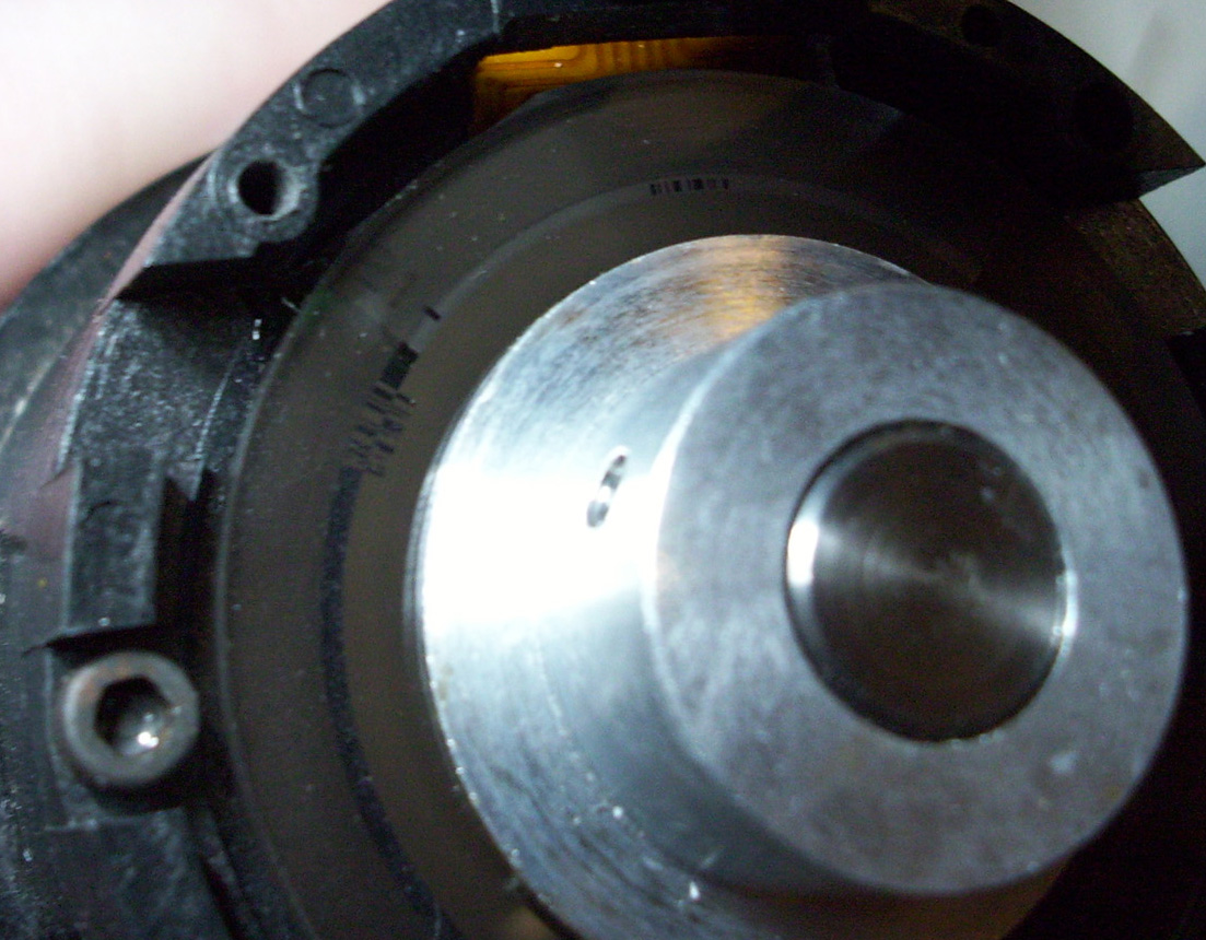
CRSPLUS Robot - EG&G DC SERVO Motor & Encoder The CRSPLUS series robots use "EG&G TORQUE SYSTEMS - PM FIELD DC SERVO MOTORS". This company is now called "Torque Systems" I believe. (http://www.torquesystems.com) The Model Numbers for the CRS PLUS Robot Stock Motors are marked as "ME2110-047E".
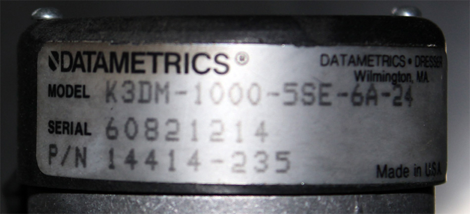
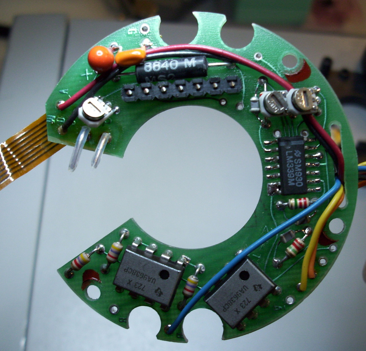
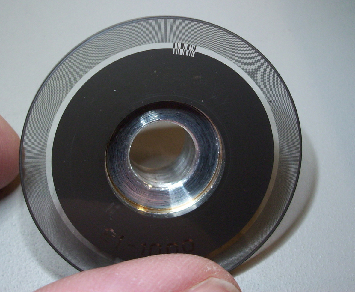
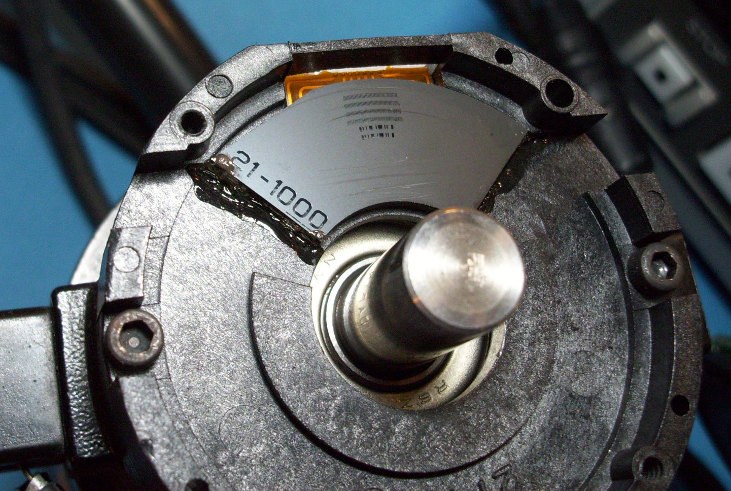
The Encodes are marked with the Model Number "C21-0445-DM-1000". These are 1000 count Incremental Optical Encoders by the company Datametrics. An alternative subsitiute Encoder is the 1000 Count "DATAMETICS" brand encoder Model # "K3DM-1000". A subsitute DC Servo Motor is the "TORQUEMASTER 2100 Series" motors available from the Torque Systems website.
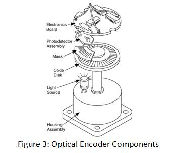
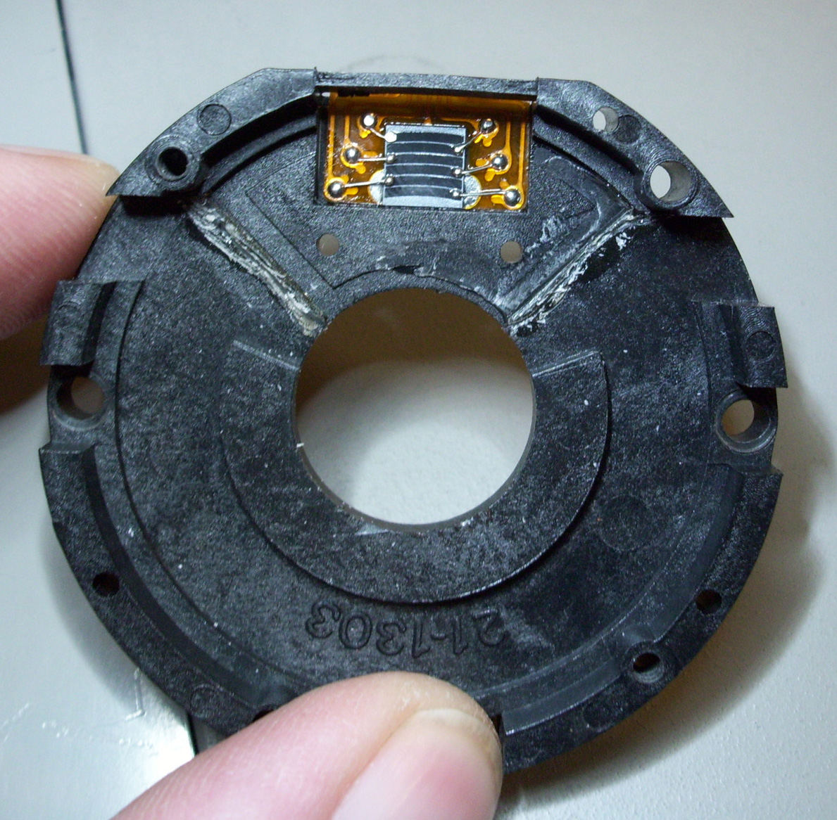
The Encoders Explained Incremental Optical encoders are sensors capable of generating digital signals in response to rotary movement. They are employed to convert the rotary movement into electrical signals and to obtain position and speed measures. The encoder generates a signal for each incremental change in position . In conjunction with mechanical conversion devices, such as rack-and-pinions, measuring wheels or spindles, incremental encoders can also be used to measure linear movement. With optical encoders, a grating disc made of metal or glass associated with a mask interrupts an infrared beam emitted by a transmitting gallium arsenide diode.
The number of gratings (increments ) determines the system ‘s resolution , ie . the number of increments per rotation. Every time the infrared beam is interrupted, this is registered by a receiver and then processed electronically.
To make the detection less sensitive to the light level, the receiver uses a differential measure between two photodiodes: one lighted and the other masked. The result is a square wave output signal as shown in the images below.
Two shifted photosensitive diode arrays deliver squared signals ( A and B) in quadrature. The Phase shift (90°) of signals A and B makes possible to determine the direction of rotation. In one direction, during the rise of singal A, signal B is equal to 1. In the other direction, Deuring the rise of signal A, signal B is equal to 0.
The Z or singnal zero comprises only one transparent window delivering one signal with a full revolution of the motor shaft. This signal is gated in synch with signals A and B. This zero signal determines a position of reference and allows reinitializing of the system at each turn.
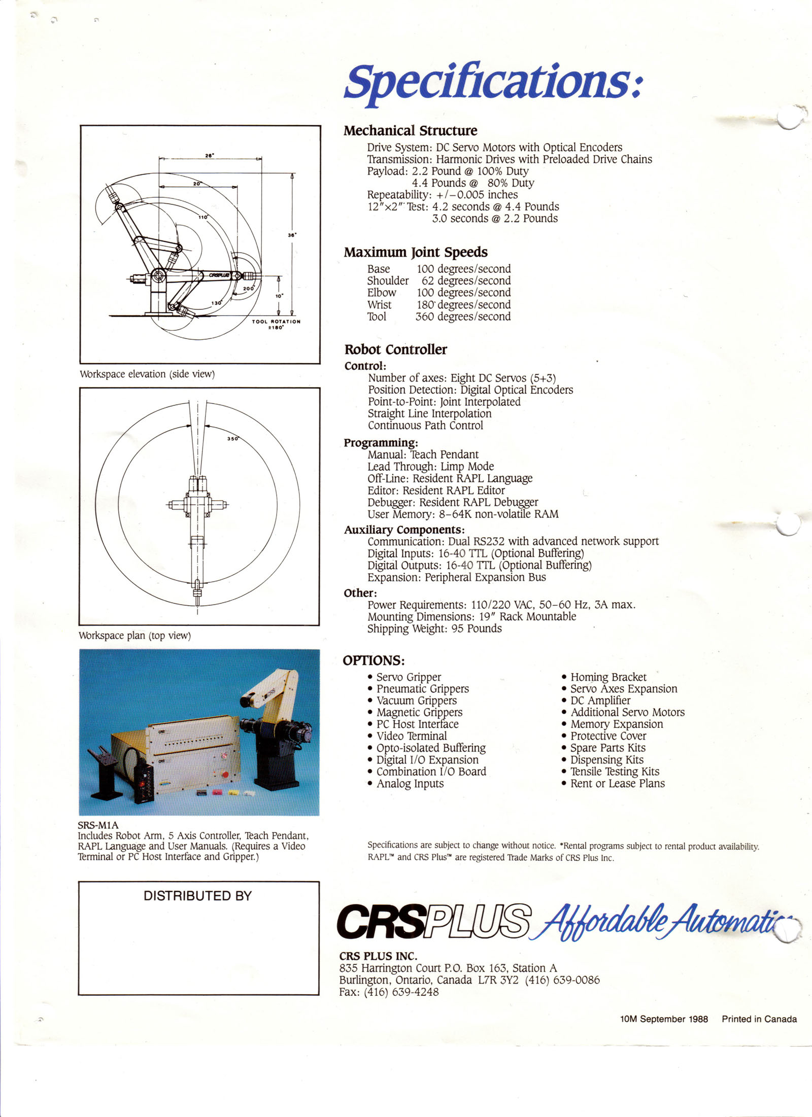
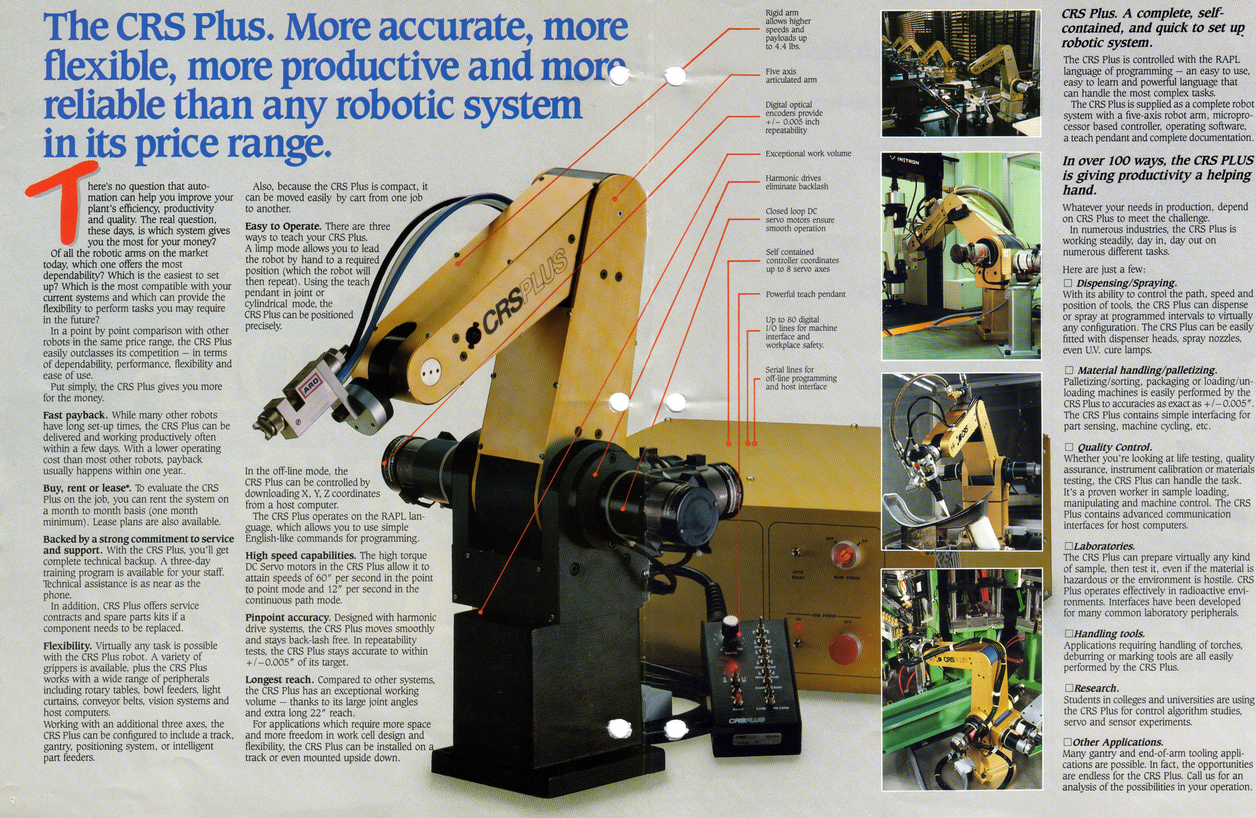
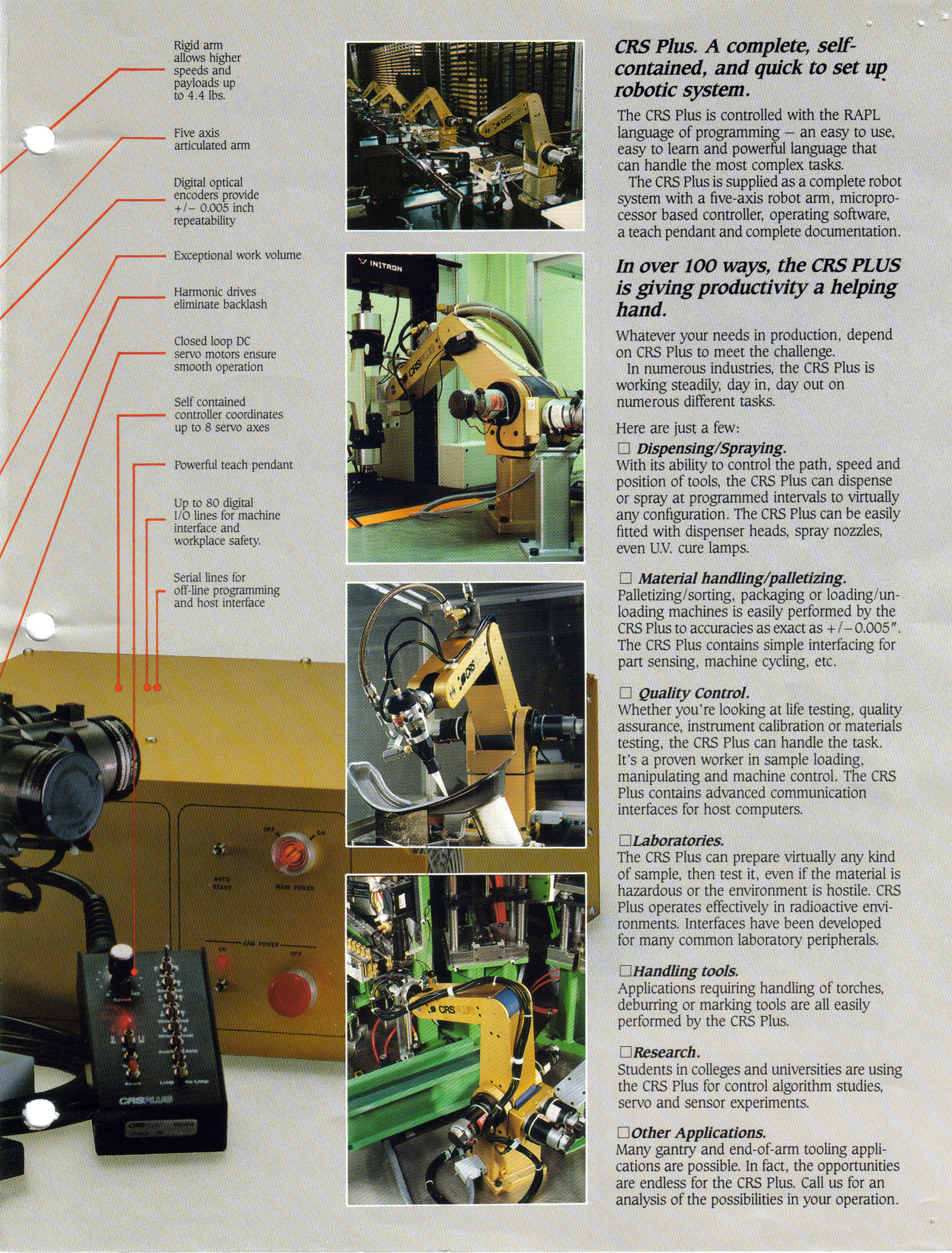
"CRSPLUS robot Series Promotional Poster"
CRS PLUS Robot System CRSPlus User & Technical Manuals Here are a series of User/Technical Manuals for the CRS Plus "SRS-M1" & "SRS-M1A" Robot systems. This includes the system schematics!! :)
"SRS-M1" Manuals SRS-M1 TECHNICAL MANUAL (.Zip Archive Approx. 40Mb) SRS-M1 TUTORIAL MANUAL (.Zip Archive Approx. 10Mb)
"SRS-M1A" Manuals SRS-M1A RAPL Programming Manual (.Zip 87Mb) SRS-M1A Service Manual(.Zip 72Mb) SRS-M1A IBM-PC_Host_Interface (.Zip 40Mb) CRSPlus Digital I/O Expansion Module (.Zip 14Mb) SRS-M1A APPENDIX B and G [Technical Manual] (.Zip 33Mb)
Miscellaneous CRSPlus Manuals CRSPlus - Controller Internal Harness Wiring (.zip) CRSPlus - LOADHEX and SAVEHEX Commands (.zip) CRSPlus - Replace Serial Device Driver (.zip) CRSPlus - ACI Interface Library - Chapter 1 (.zip) CRSPlus - MODULE Descriptions - Chapter 2 (.zip) CRSPlus - ROBCOMM-II V2.0 Software Help-File (.Zip)
-= CRS ROBOTICS - Additional Resources =- Another website on CRS Robotics for you to check out is Gregory Graham's CRS Robotics Page. Link below: Gregory Graham was a Professor at California State University, Los Angeles for 39 years. His Experience and knowledge is no doubt a welcomed asset to the CRS Robotics community.
-=CRS ROBOTIC ARM YAHOO GROUP =- Please Join my CRS ROBOTIC ARM Yahoo Group! Let's all connect and share our Resources to get our CRS Robots up and running. http://groups.yahoo.com/group/CRS_ROBOTIC-ARM_GROUP
|
||
|
||


