|
Current Time:
|
|
|
|
|
Gerry's Electronics & Robotics Laboratory -=SOLDERING=- -=MY BENCH=- -=MY ROBOTS=- -=PCB FAB=- -=CHIPPERY=-\
|
|
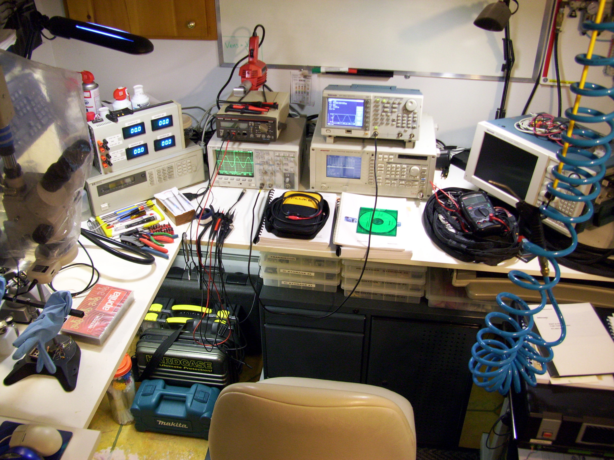
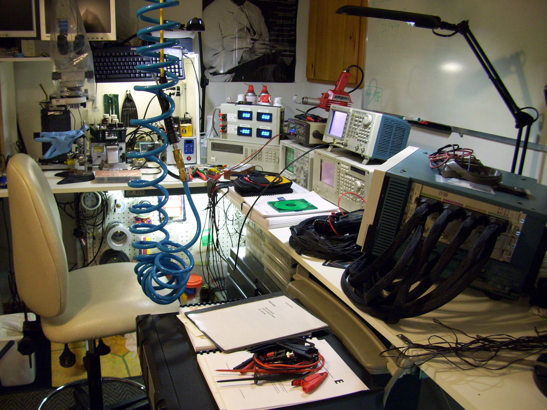
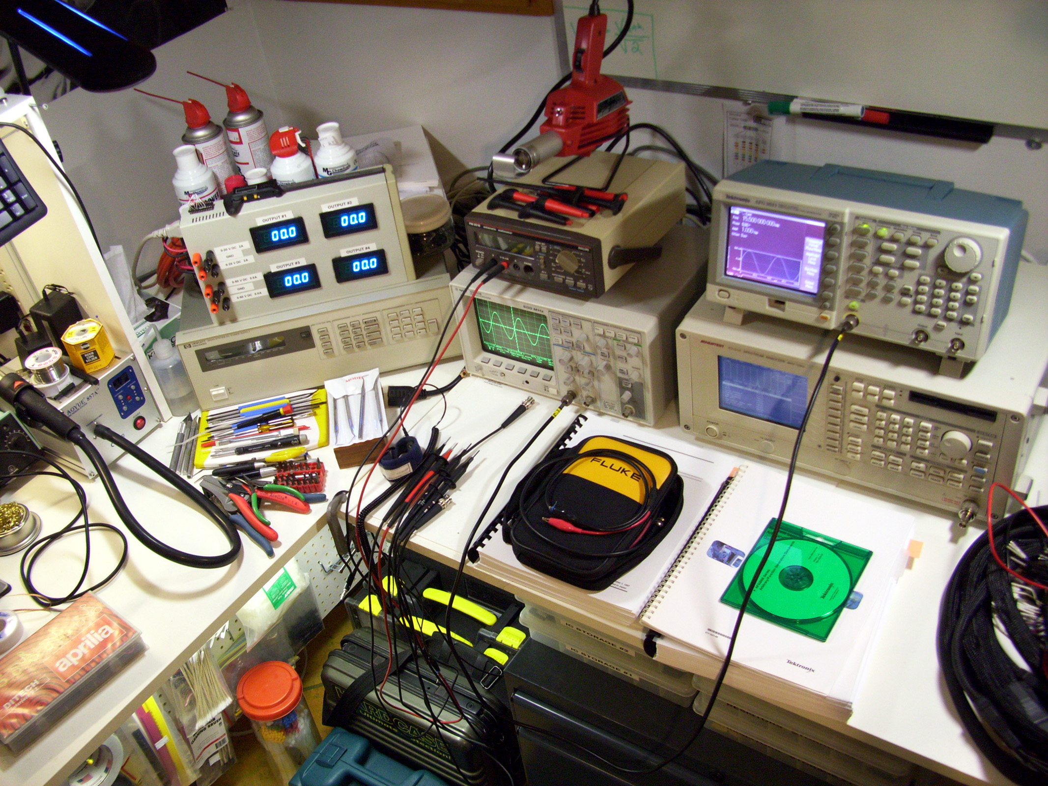
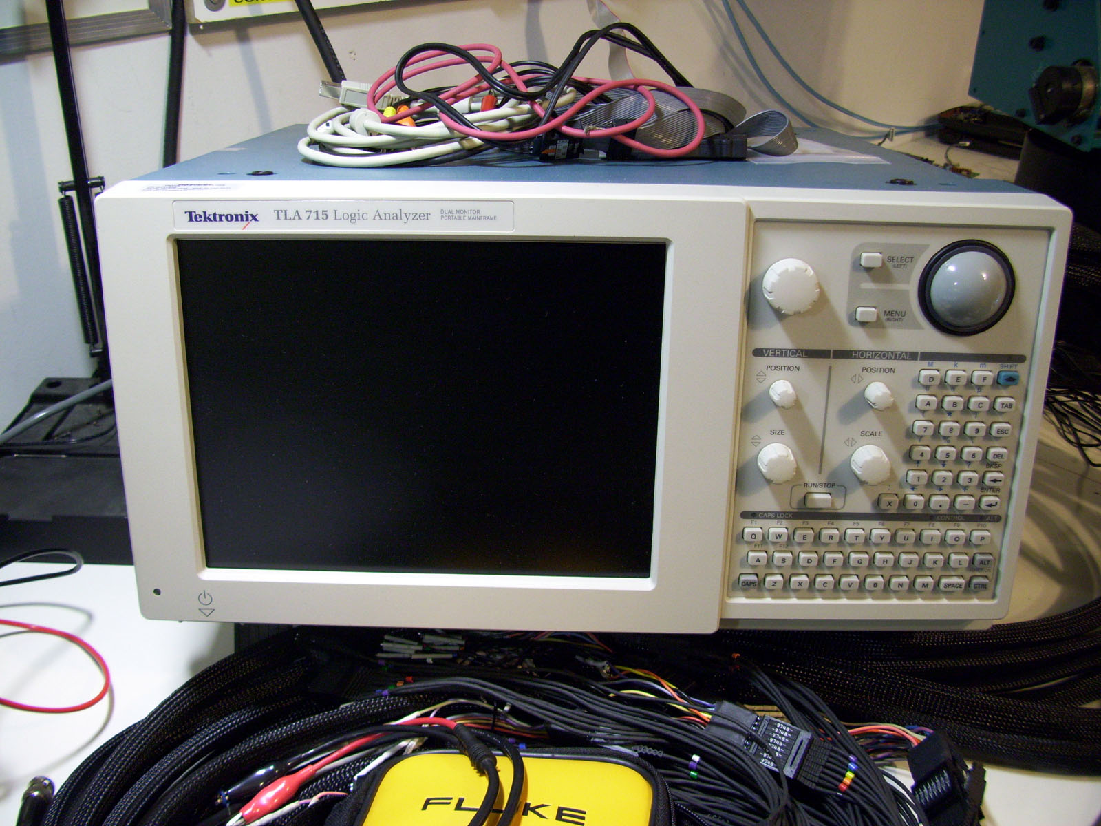
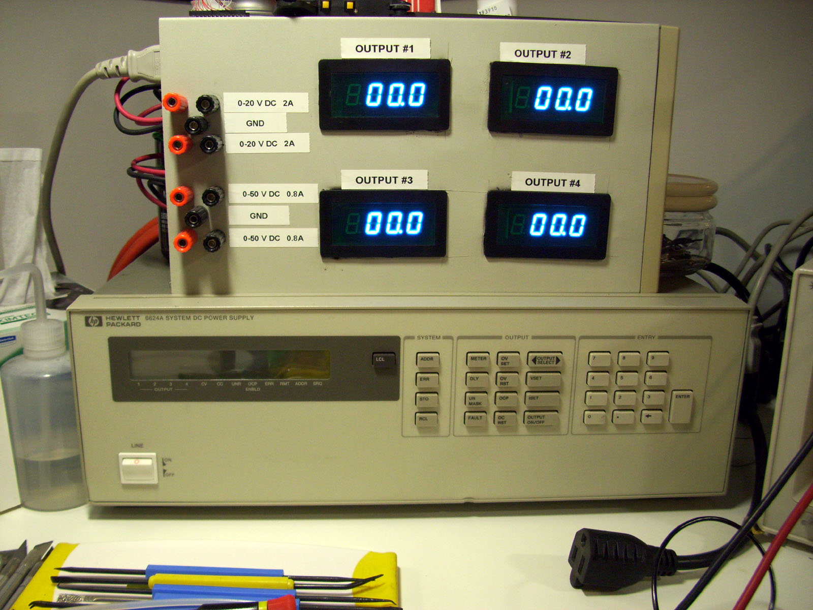
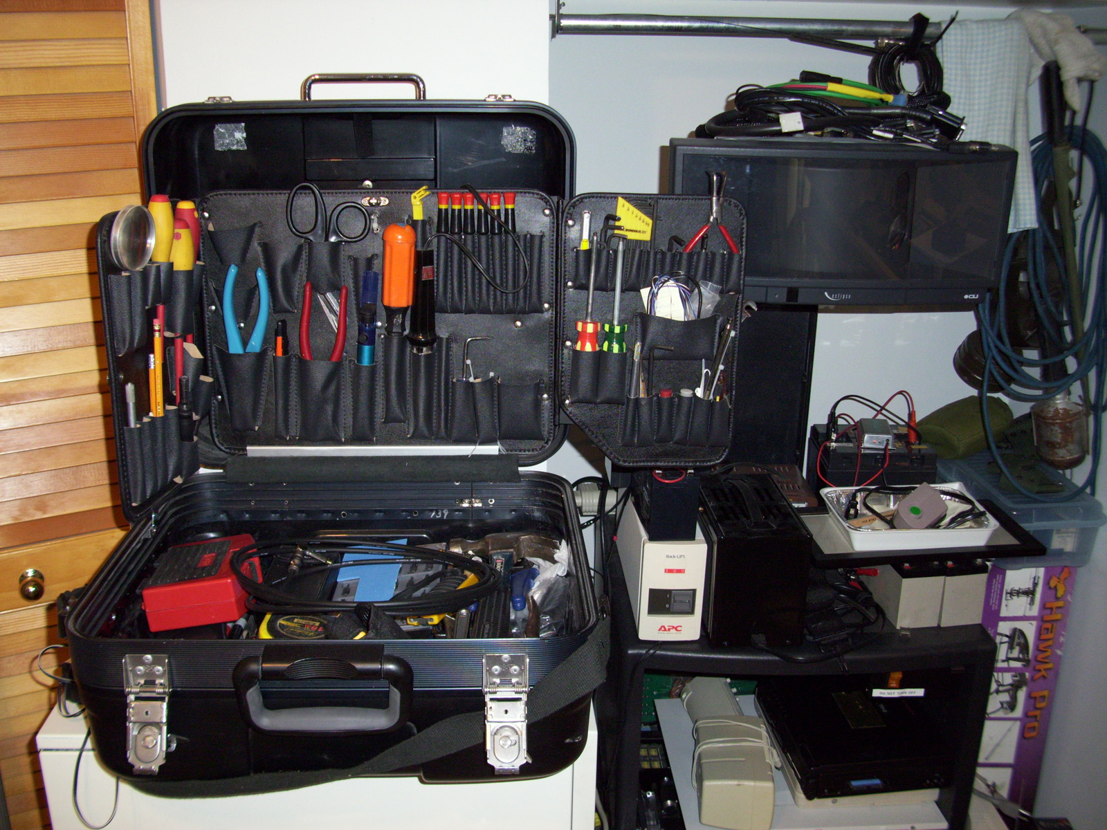
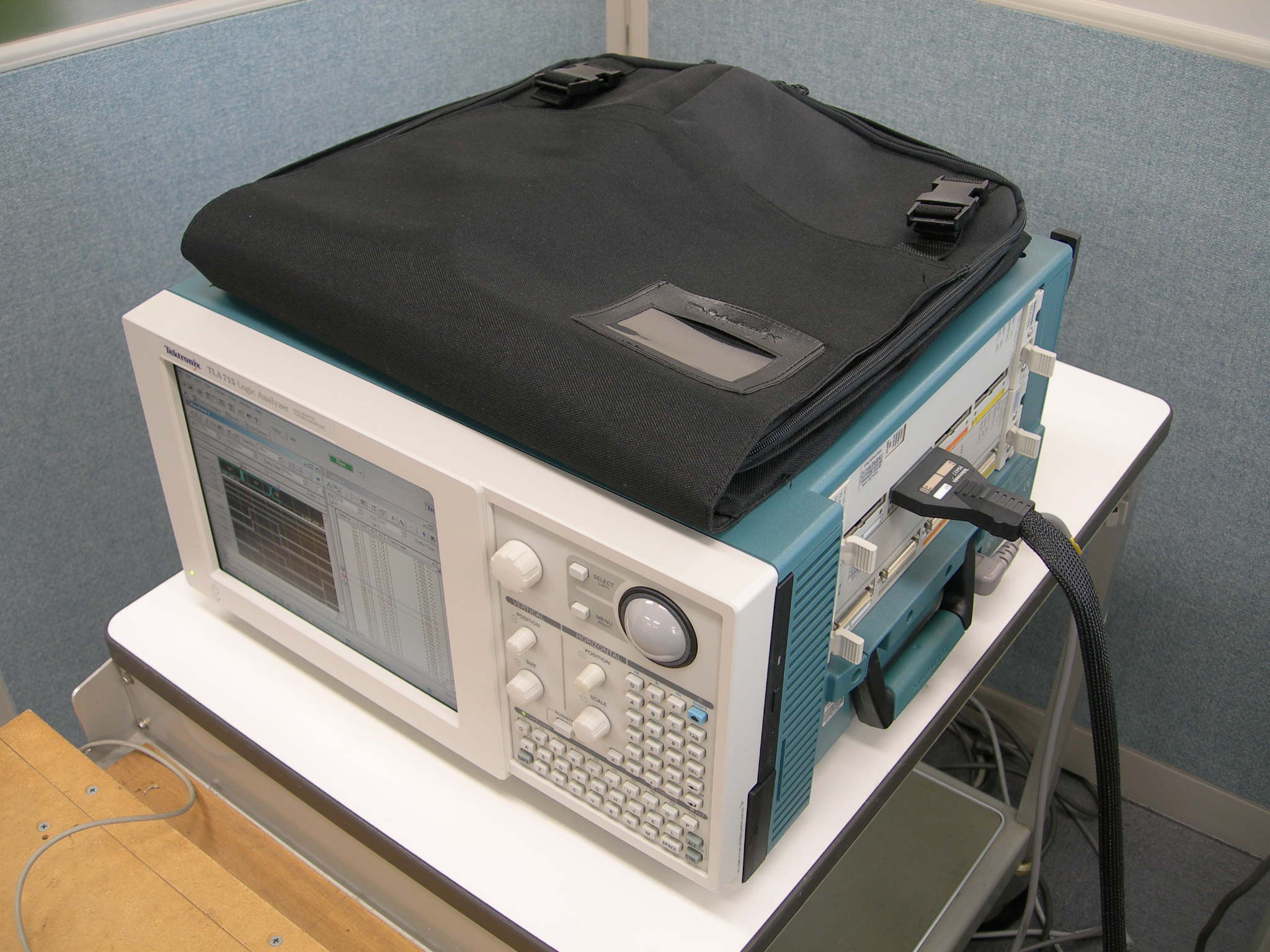
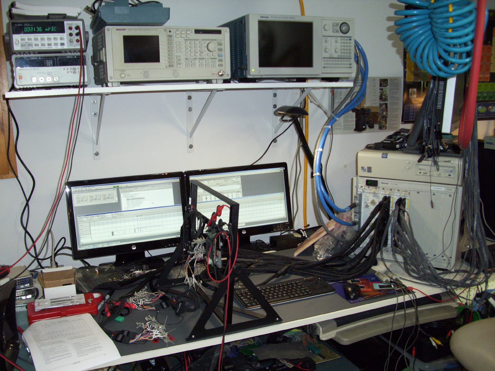
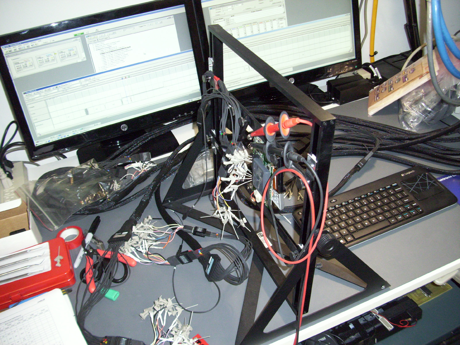
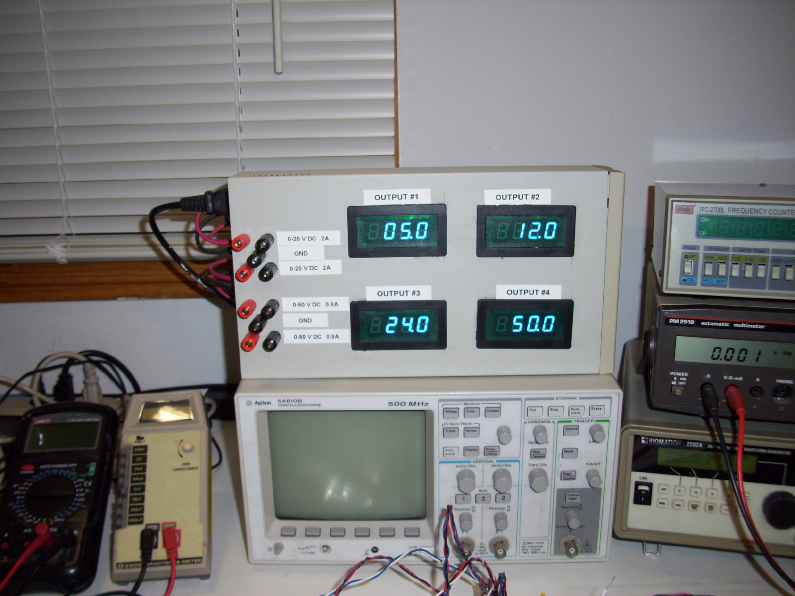
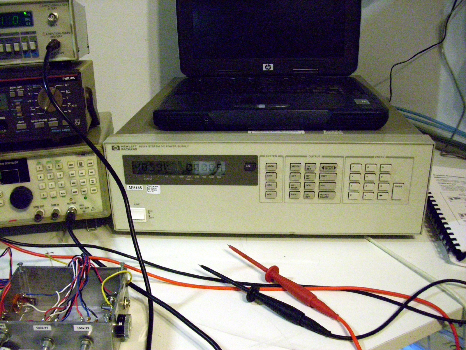
-= My Electronics Bench - Tools and Testing Gear =- This is my Electronics bench where I do most of my circuit prototyping and diagnostics. My Diagnostics & Test equipment is constantly growing. Currently I have an Agilent/HP 54610B 500Mhz Oscilloscope with the GPIB to RS232 adapter for image capturing. I also have a 25Mhz Tektronix Function Generator / Frequency counter, and an HP 4CH Programmable Power supply. I built a Display panel for the 4 separate Voltage output channels, so that I can monitor the voltages of all 4 outputs simultaneously. The stock Monochrome LCD display on this HP unit is very small and dim and only shows one output at a time. I just recently purchased a used and broken Tektronix TLA715 Logic Analyzer Portable Mainframe with dual VGA monitor support. This little Badboy of a unit will let me use various Input/Output Modules that plug into the side of the units enclosure. Similar to how a CD-ROM slides into your PC Tower, just much bigger :). The 2 Modules I have are 136 Channel Logic Analyzer input Modules. So combined, I have 272 Channels for Logic Analysis. I also have a 4-Channel Digital Oscilloscope Module to use with this machine. I have expanded this even further by interfacing the mainframe to my TLA Expansion Box which allows me to interface more than 2 Modules to the Mainframe unit. Anyhow, my current setup will allow me to perform various signal mapping and testing on chips with a large pin count, such as the older Altera MAX 208 Pin CPLD chips and later. Eventually I hope to acquire the Pulse Generator Modules with special Probe PODS to allow for some very controlled testing of various Digital circuits. Fun Stuff!! :) Here are some more shots of my Electronics Gear.
If you want to see my Soldering gear, you can go to the "Soldering" page within "Gerry's LAB". (Link at the Top of this Page)
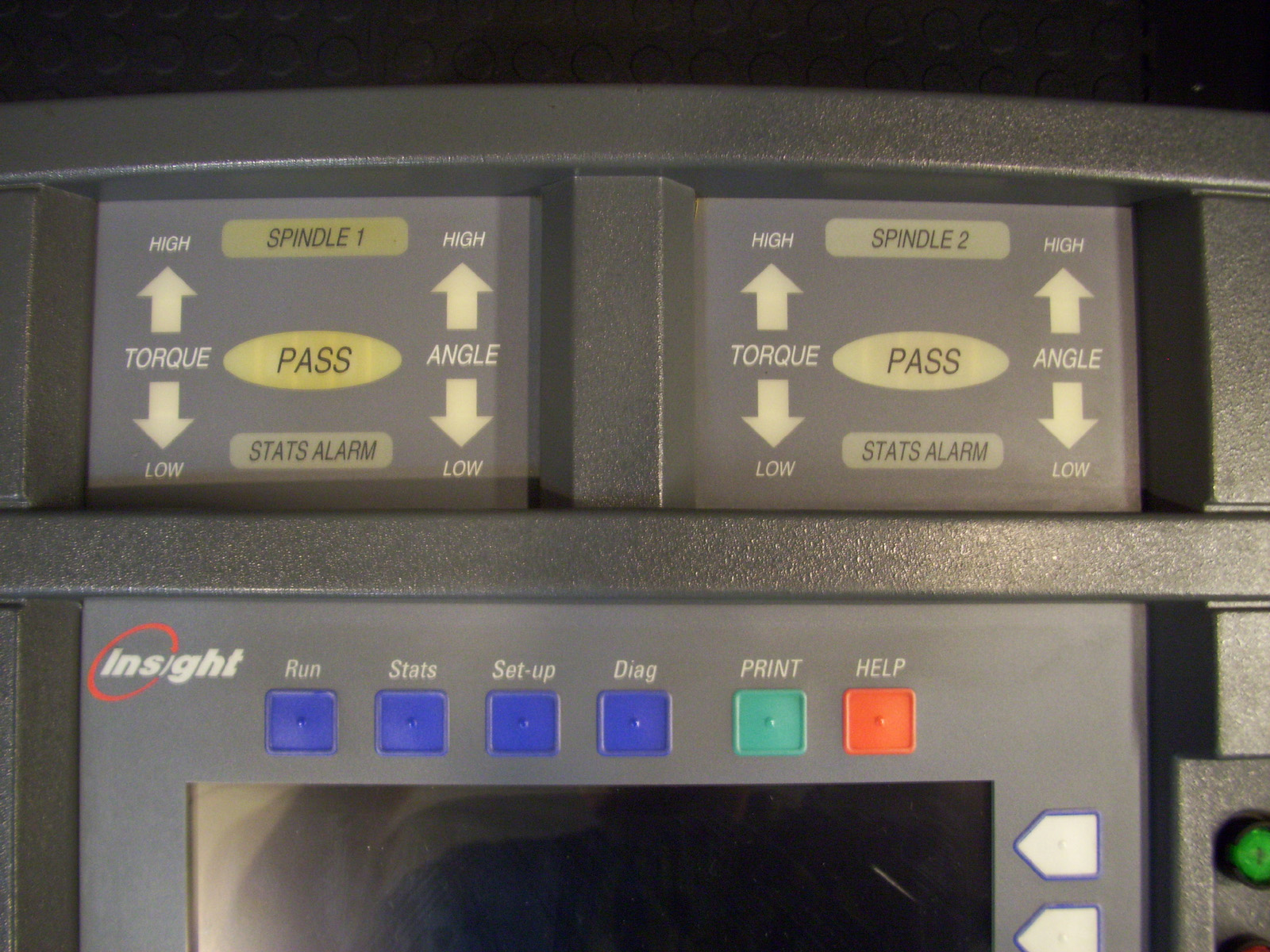
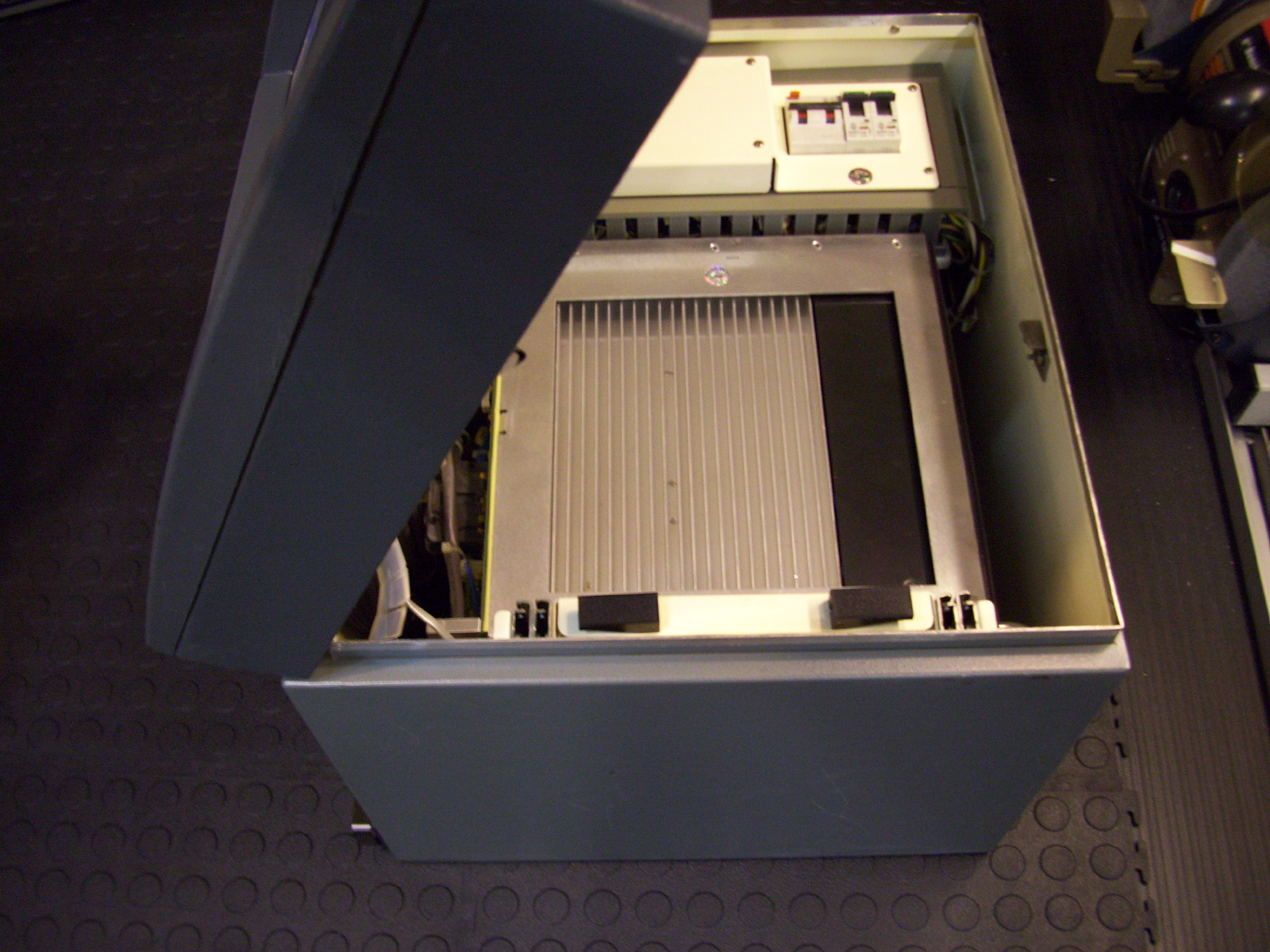
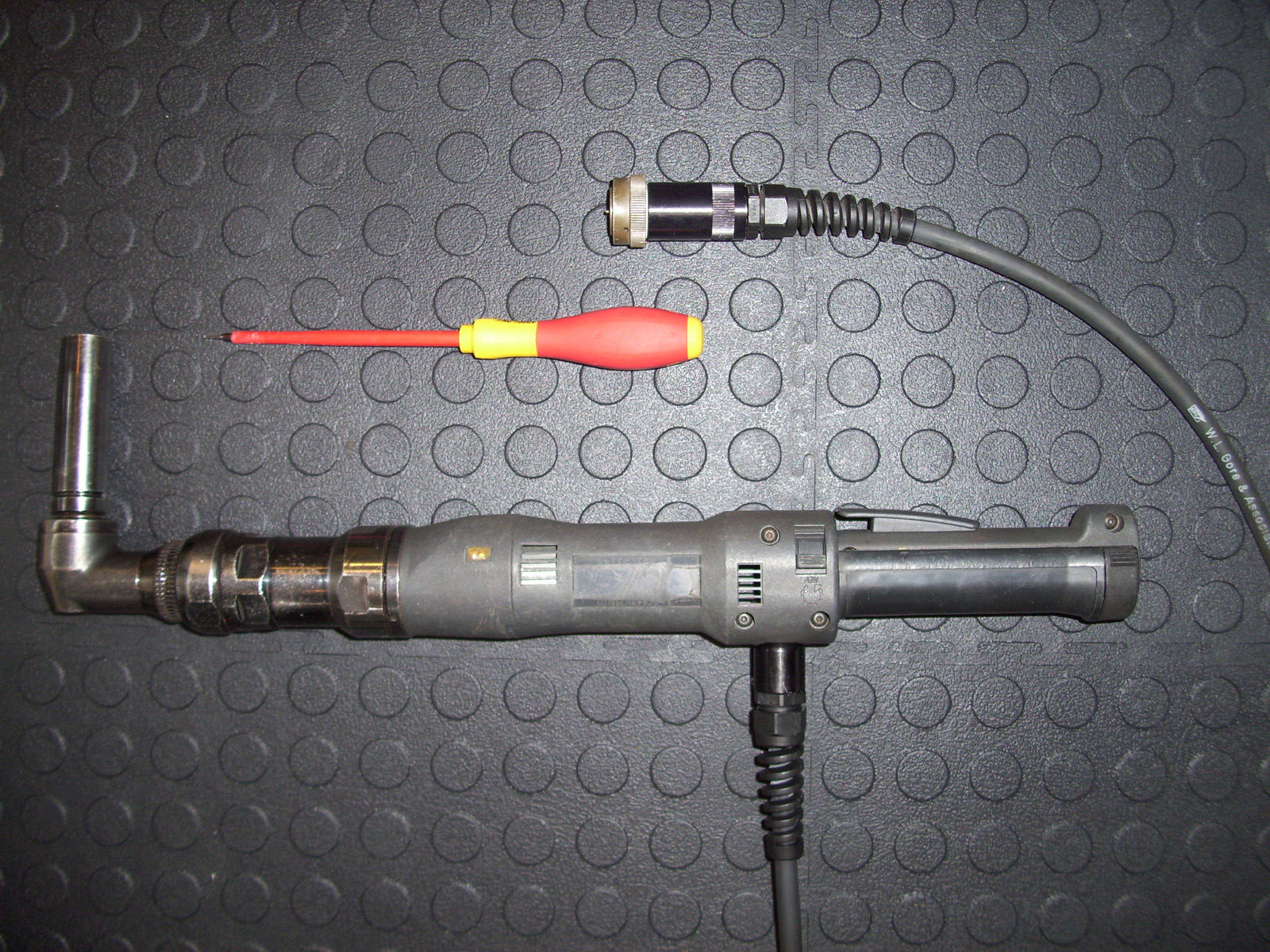
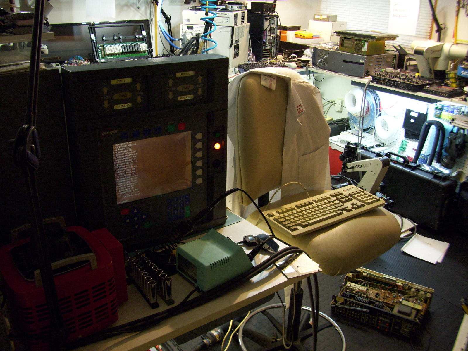
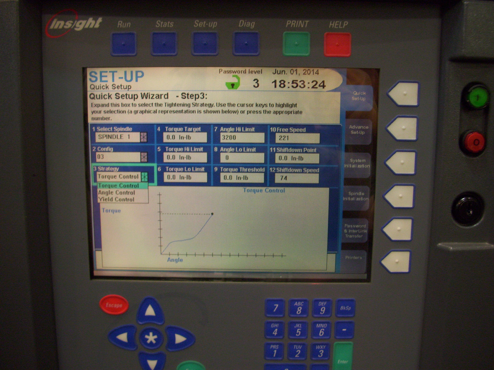
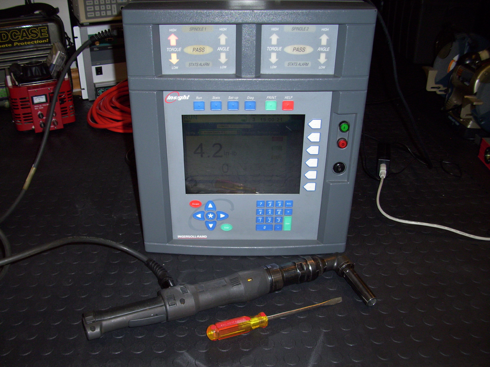
The Latest Addition to my Lab Ingersoll-Rand - INSIGHT IC "PFS2-G" DC Electric Torque Fastening Controller I managed to get my hands on a Broken Ingersoll-Rand (BRAND) "Insight PSF2-G" DC Electric Torque Wrench fastening controller. These units are used in manufacturing for analyzing and accurately setting specific Torque, Angle and Yield settings on screws, nuts and bolts that are part of a build. This is usually only used in High Volume manufacturing, but the fact that I got this unit for less than $200 I grabbed it. These controllers retailed for around $13,000.00 New back in the day. This model is from the Late 90's, early 2000 and is fairly large, about the size of a personal Safe. You can see the hand Screw Driver in the Image above for size comparison.
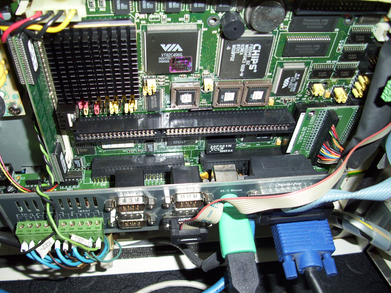
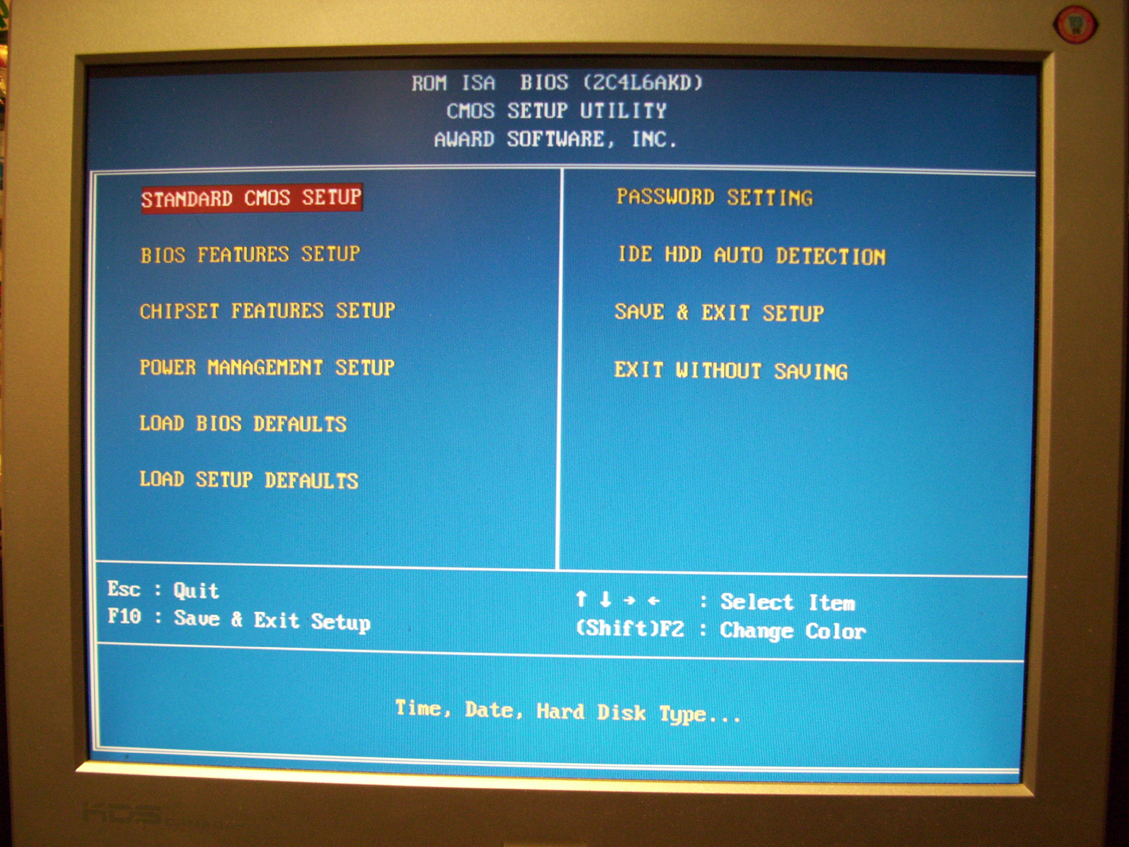
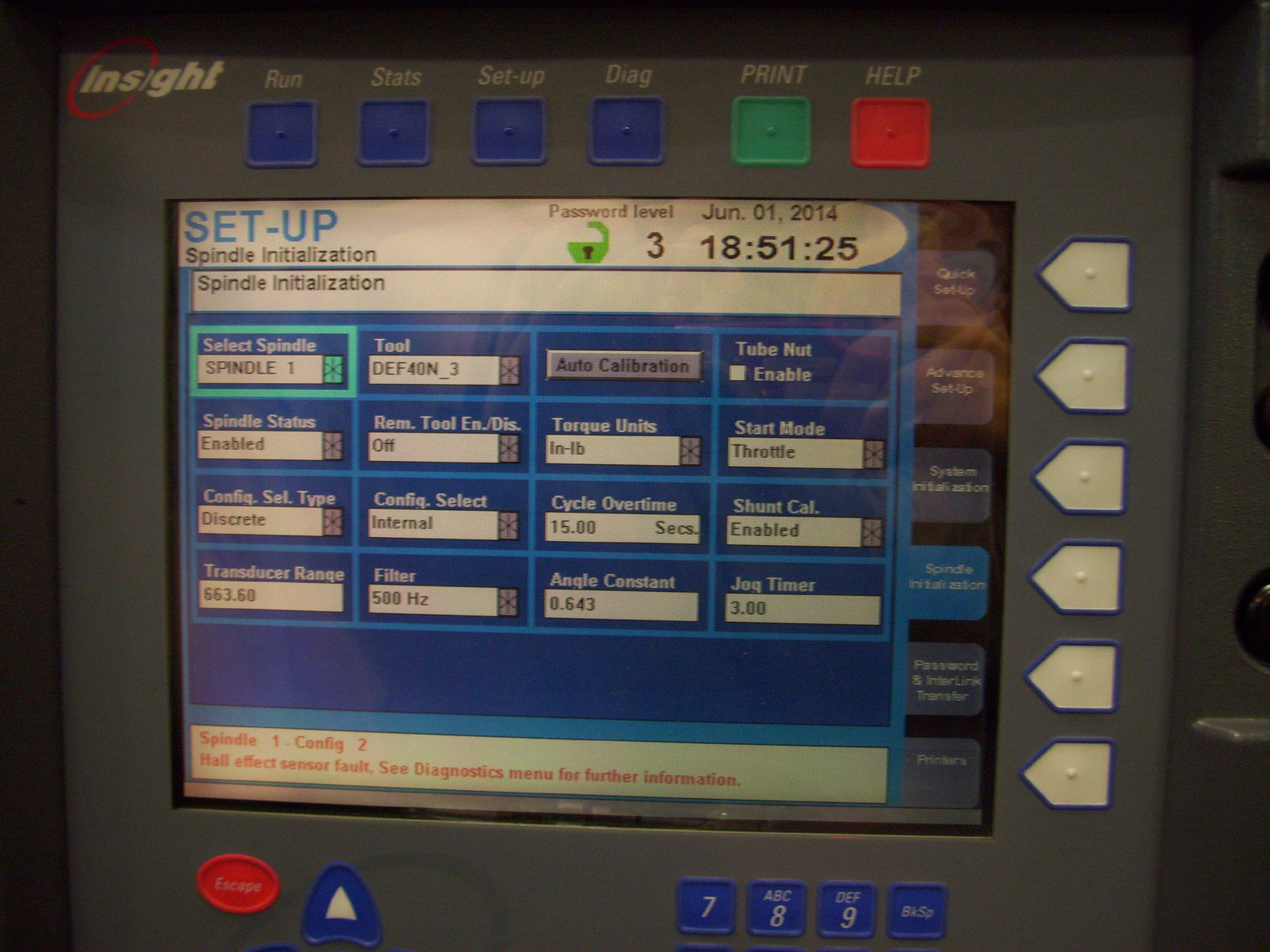
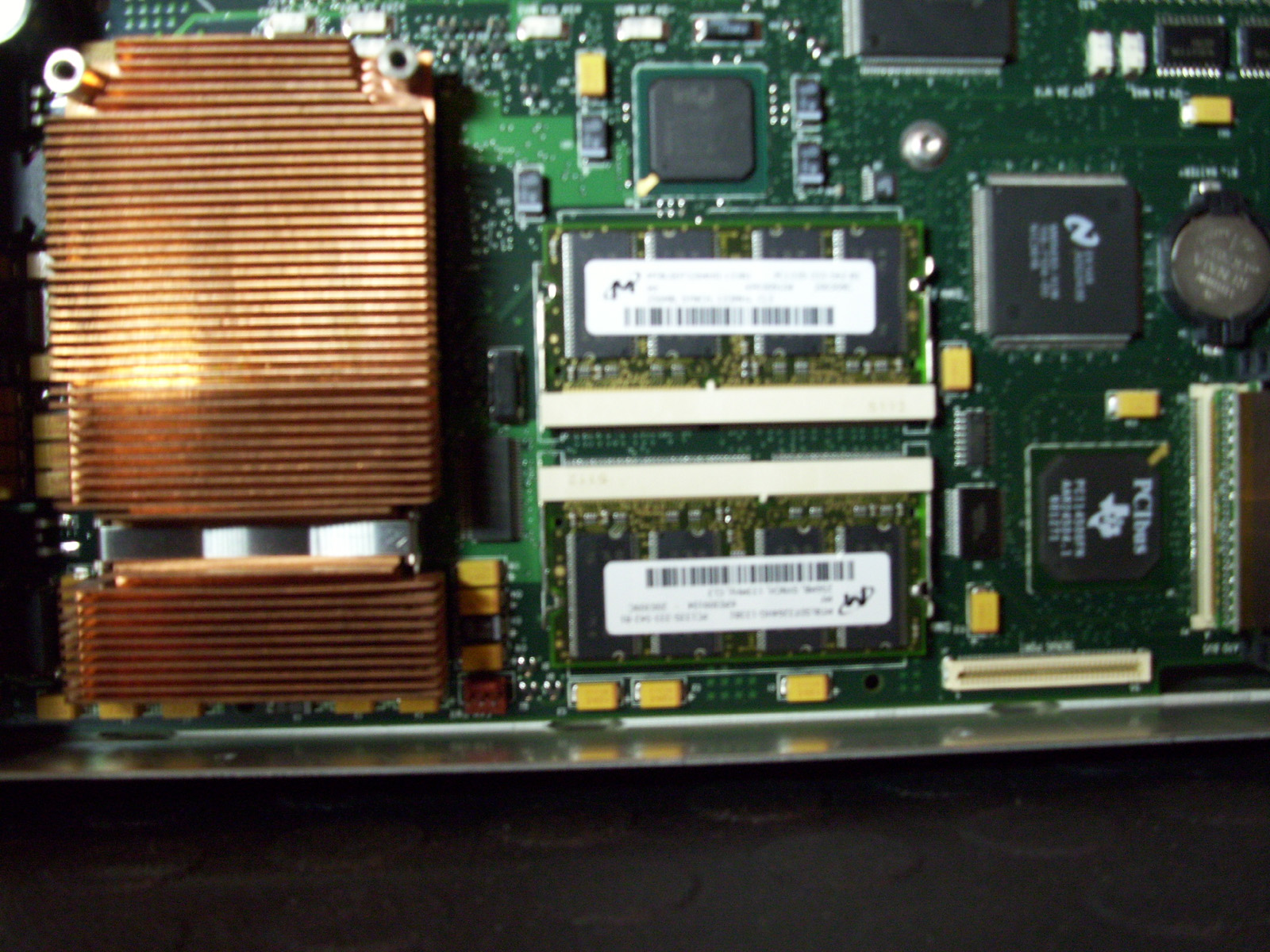
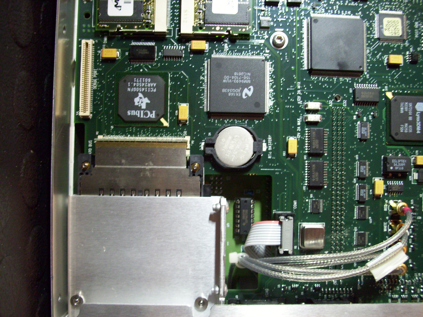
There is a micro-PC installed, an Advantech PCM-4865 motherboard Industrial Computer That runs DOS or Windows 3.1 or Windows 95. The unit is also available from Advantech as a Touchscreen package called the "PPC-100". The standard functions for the PC are Shown below: Standard PC Functions
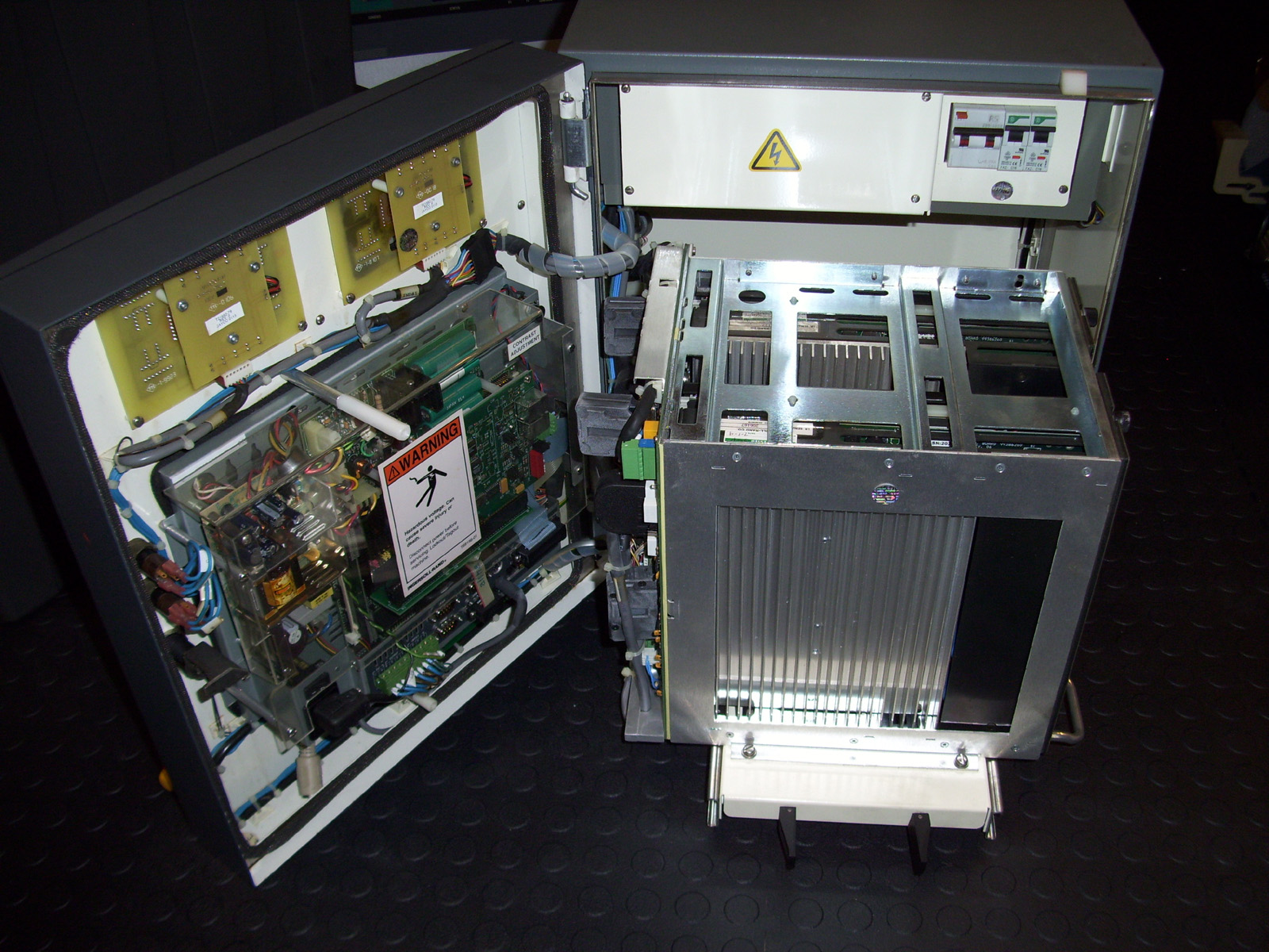
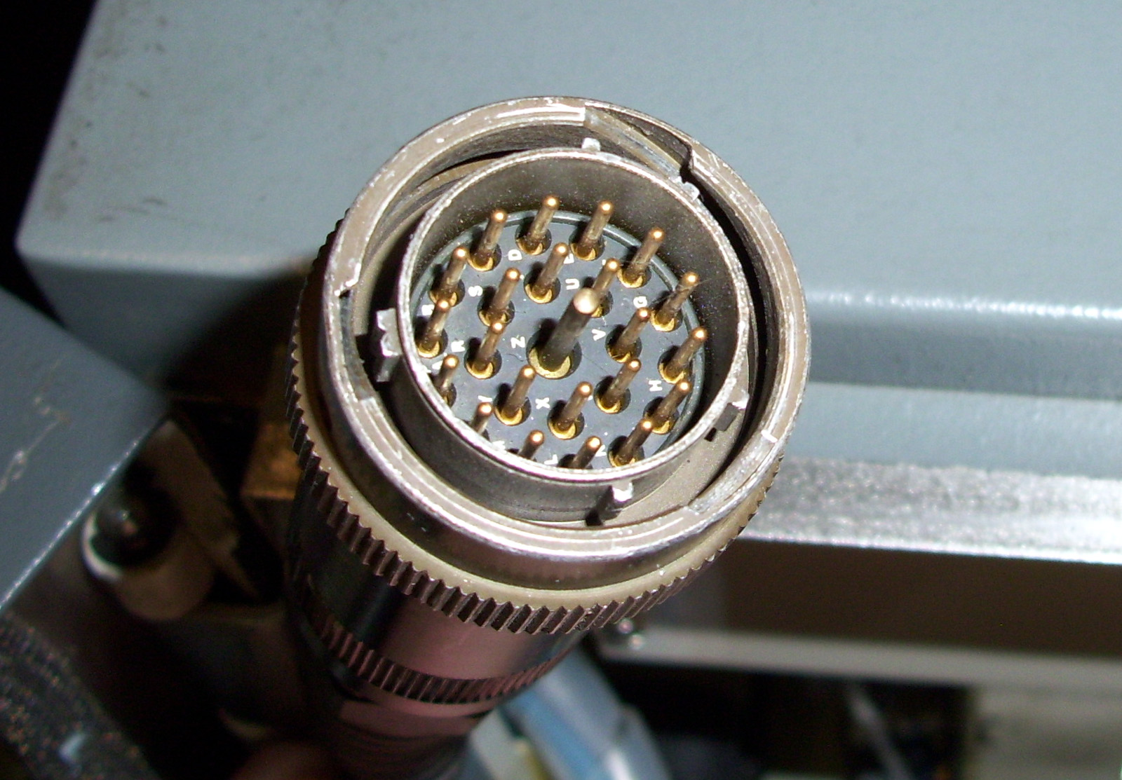
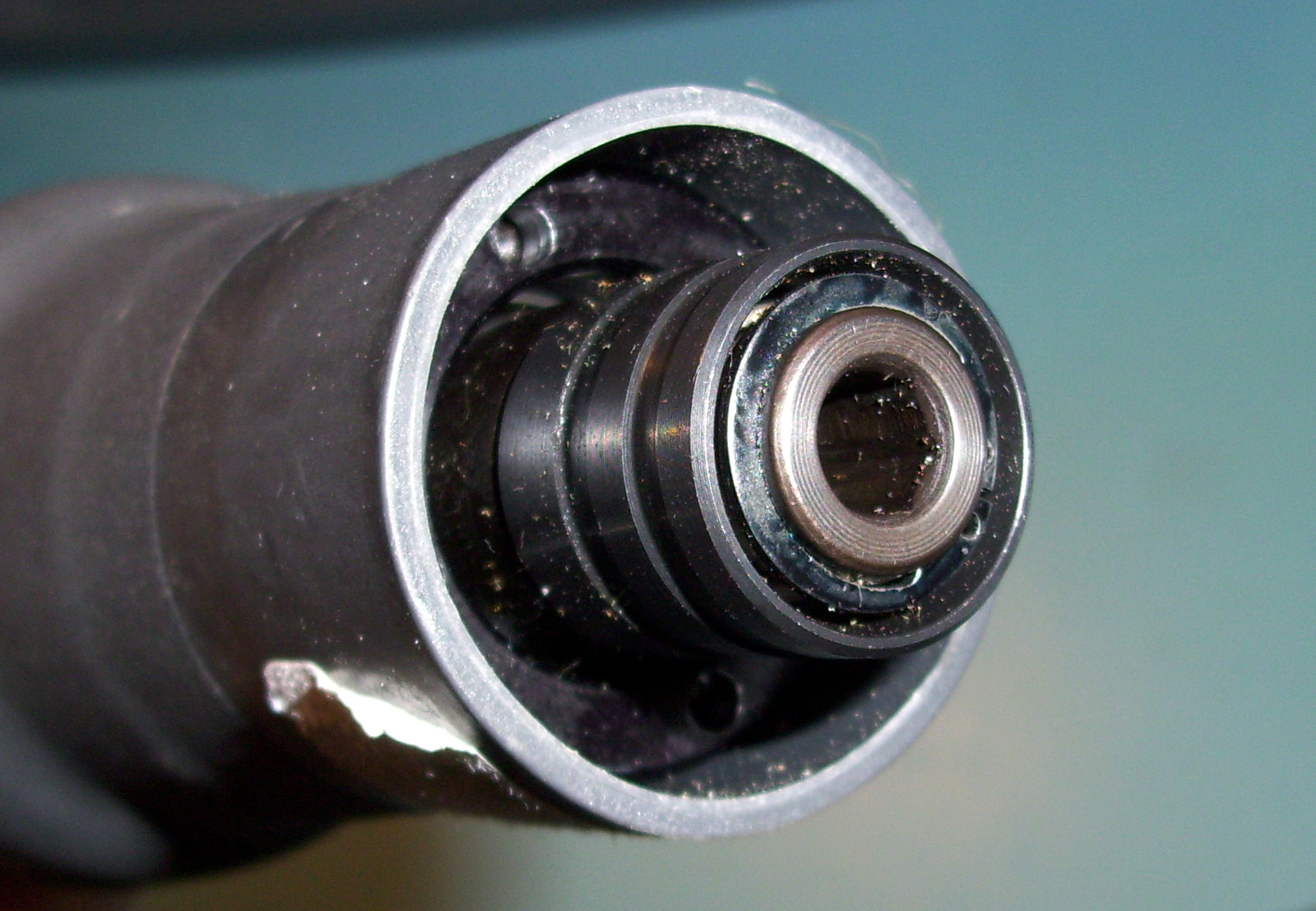
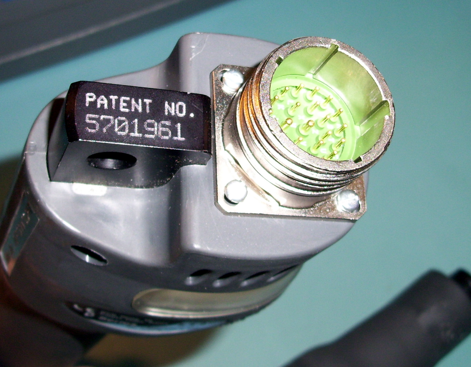
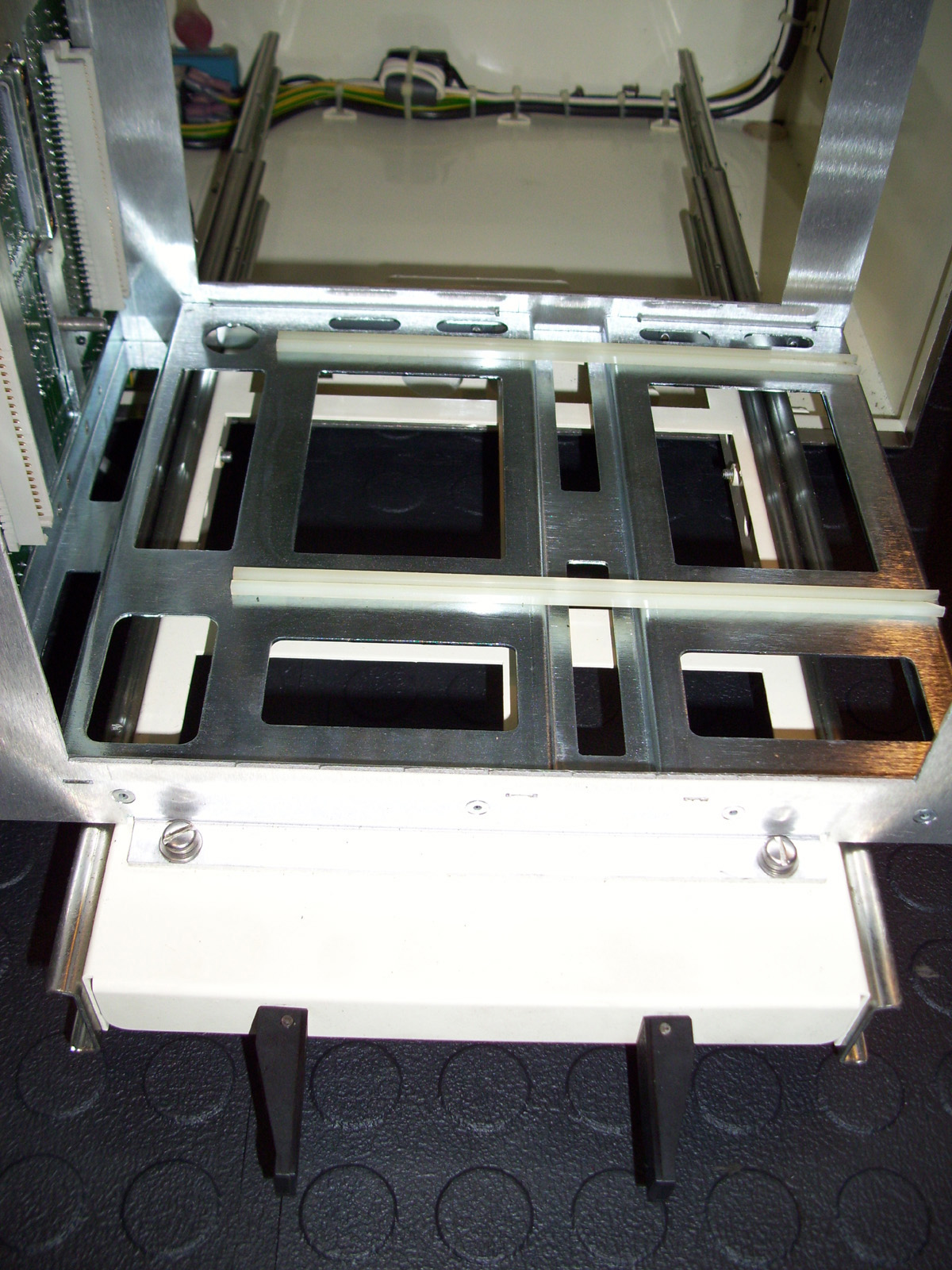
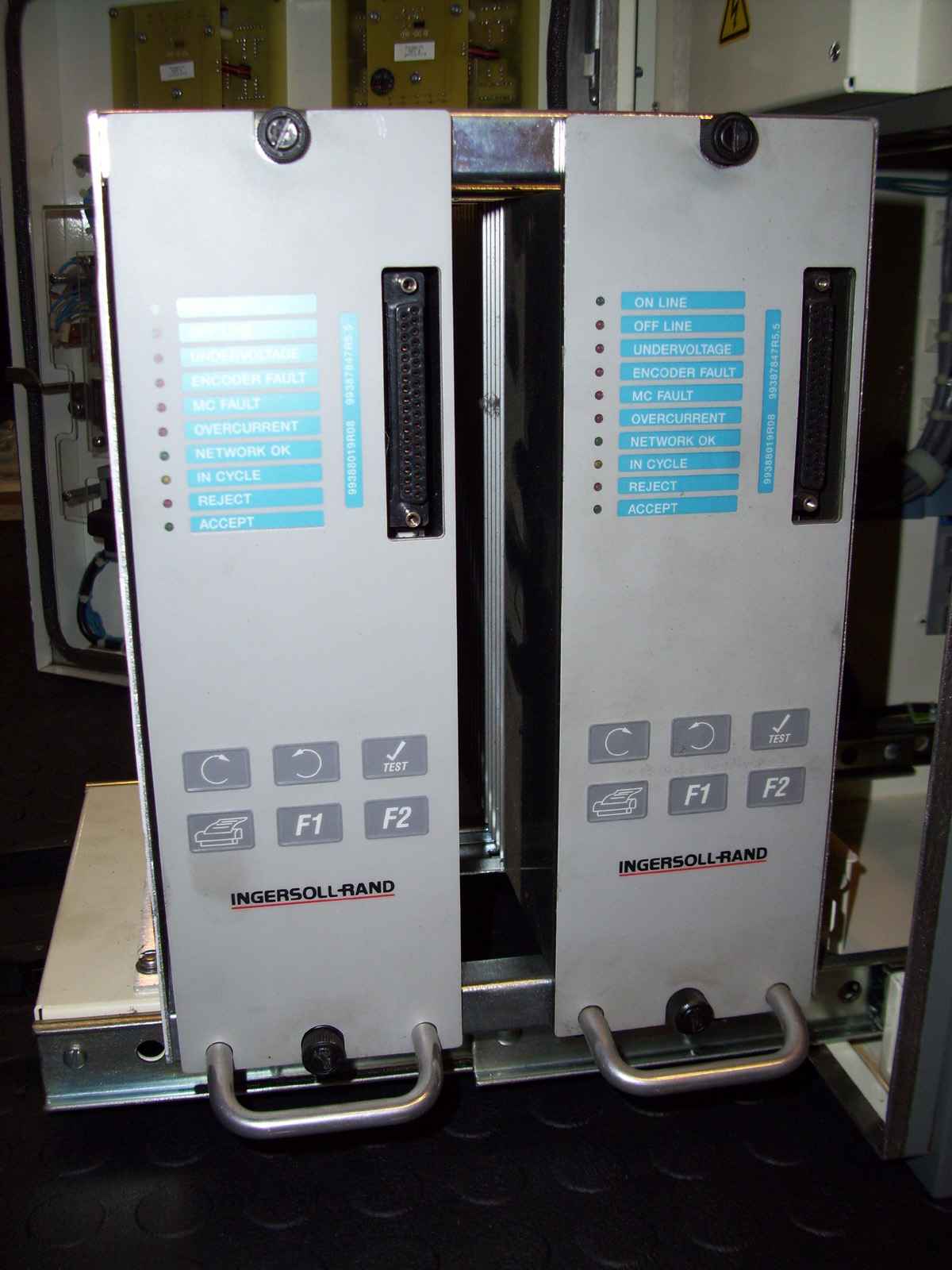
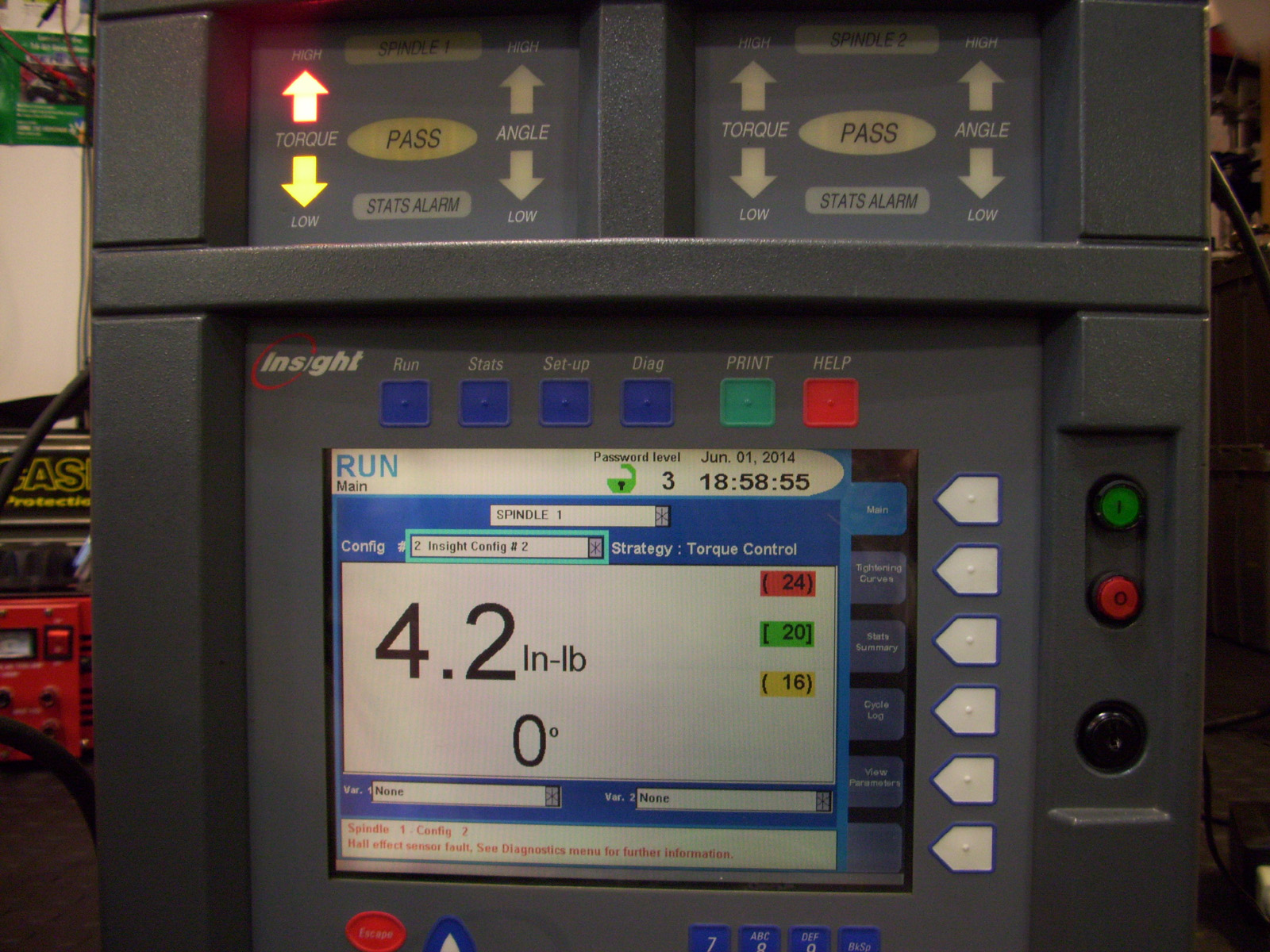
Shown below are the INSIGHT PFS2-G Torque Tools AKA "Spindles" and their Motor Drive controllers referred to as an "SMC" or "SPINDLE CONTROL MODULE" The Tools used with PFS1-G & PFS2-G Controllers must be Ingersoll Rand (D-Series) tools. They are driven by Motor Drive modules called an "SCM" or "SPINDLE CONTROL MODULE". The controllers below are both Single channel units and therefore only have one SMC module installed. This makes the unit much smaller and obviously much lighter, around 60 Lbs. The 2 Channel controllers weigh in at about 105 Lbs.
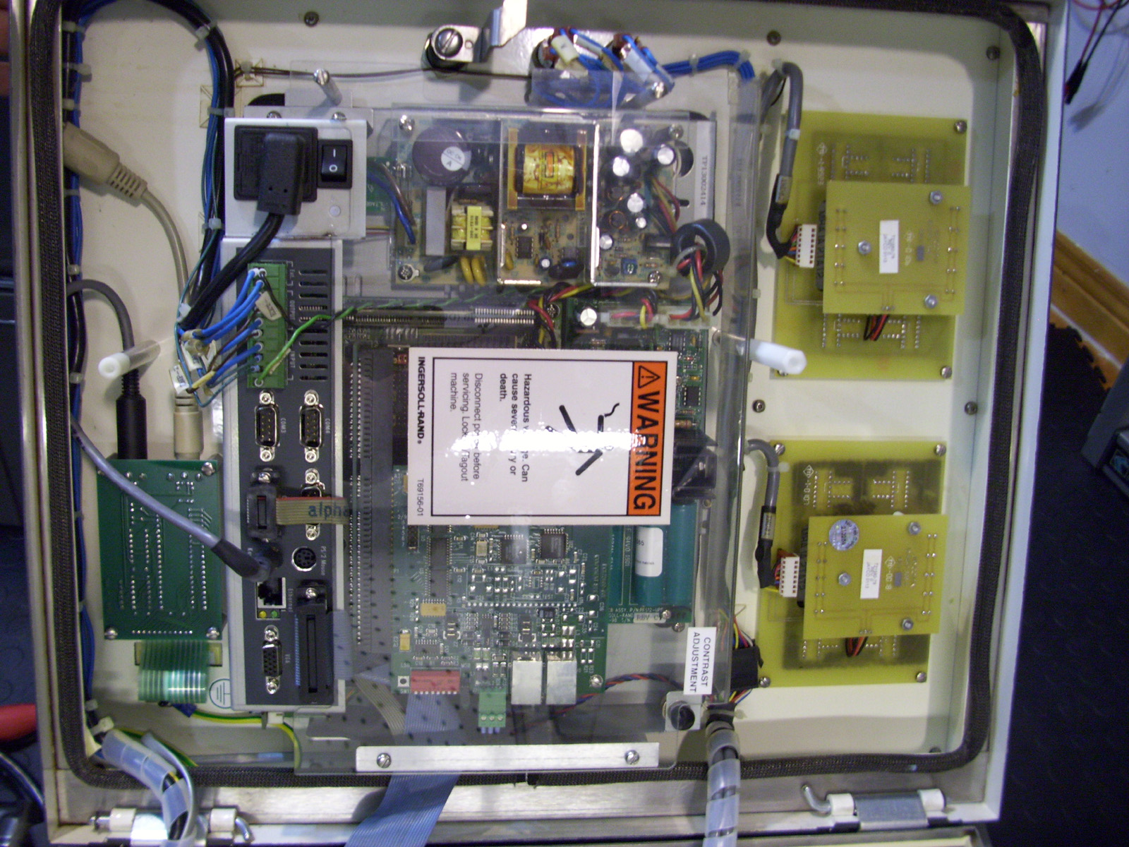
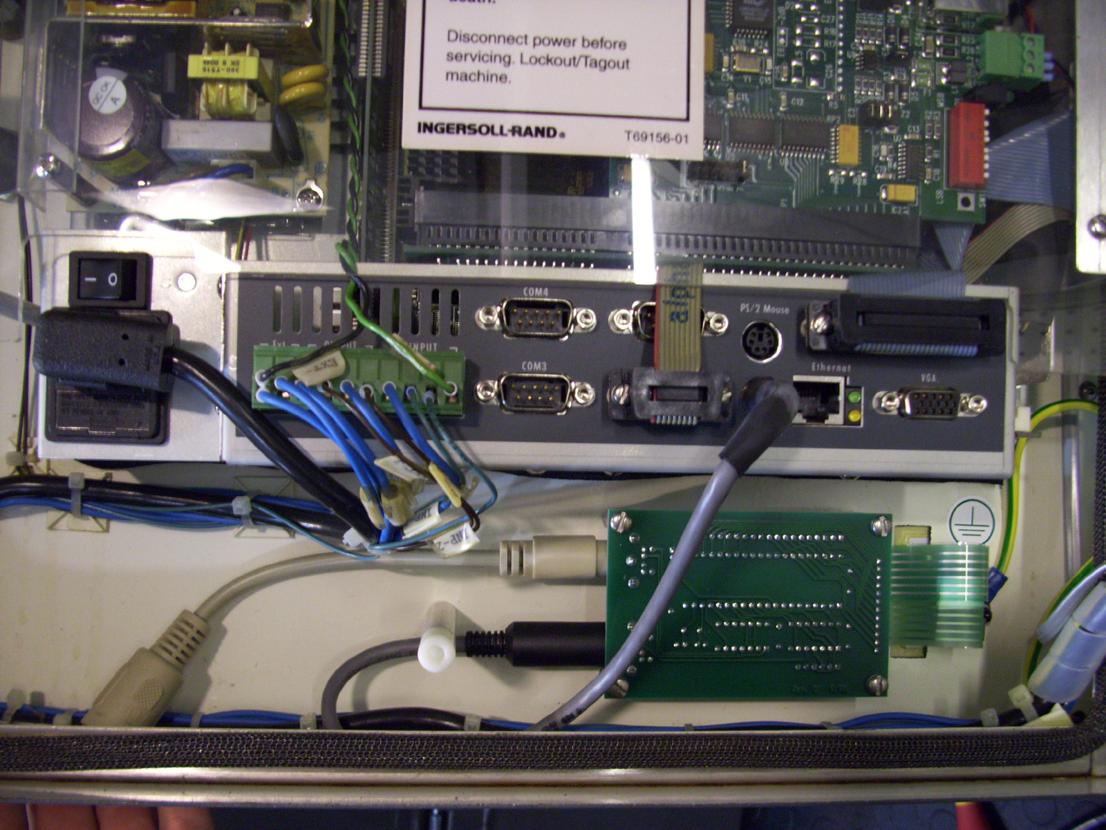
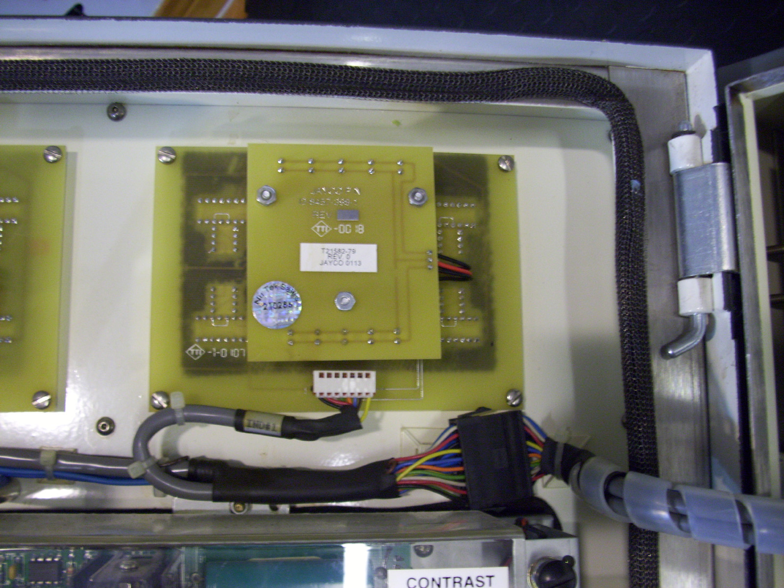
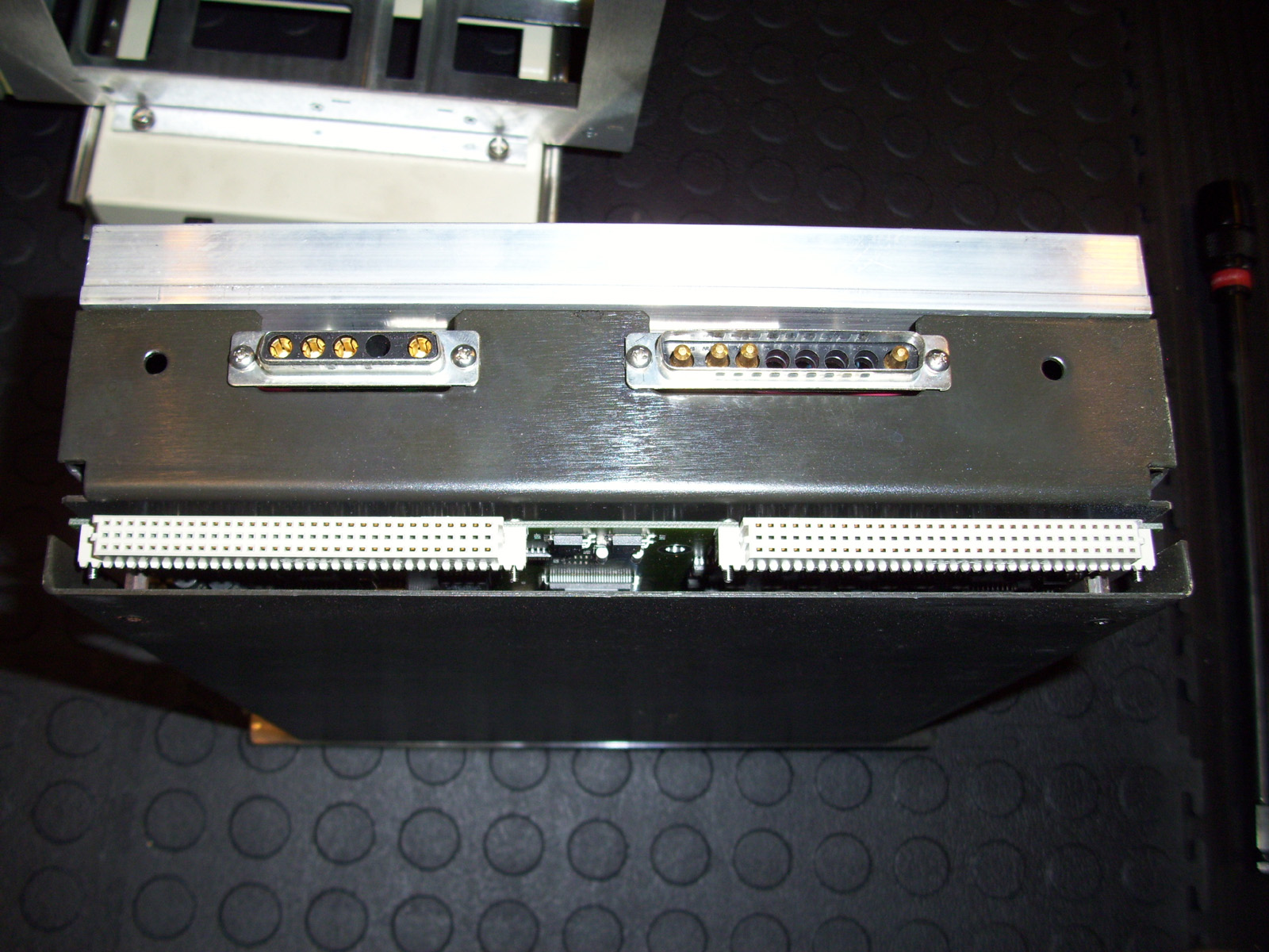
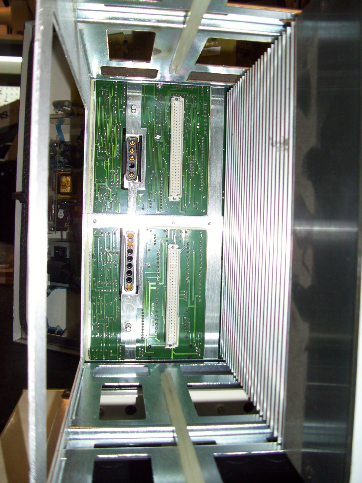
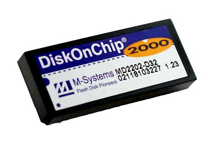
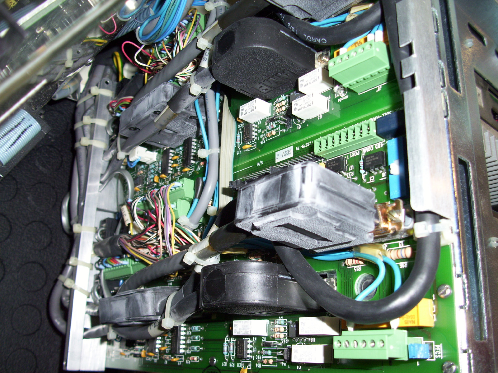
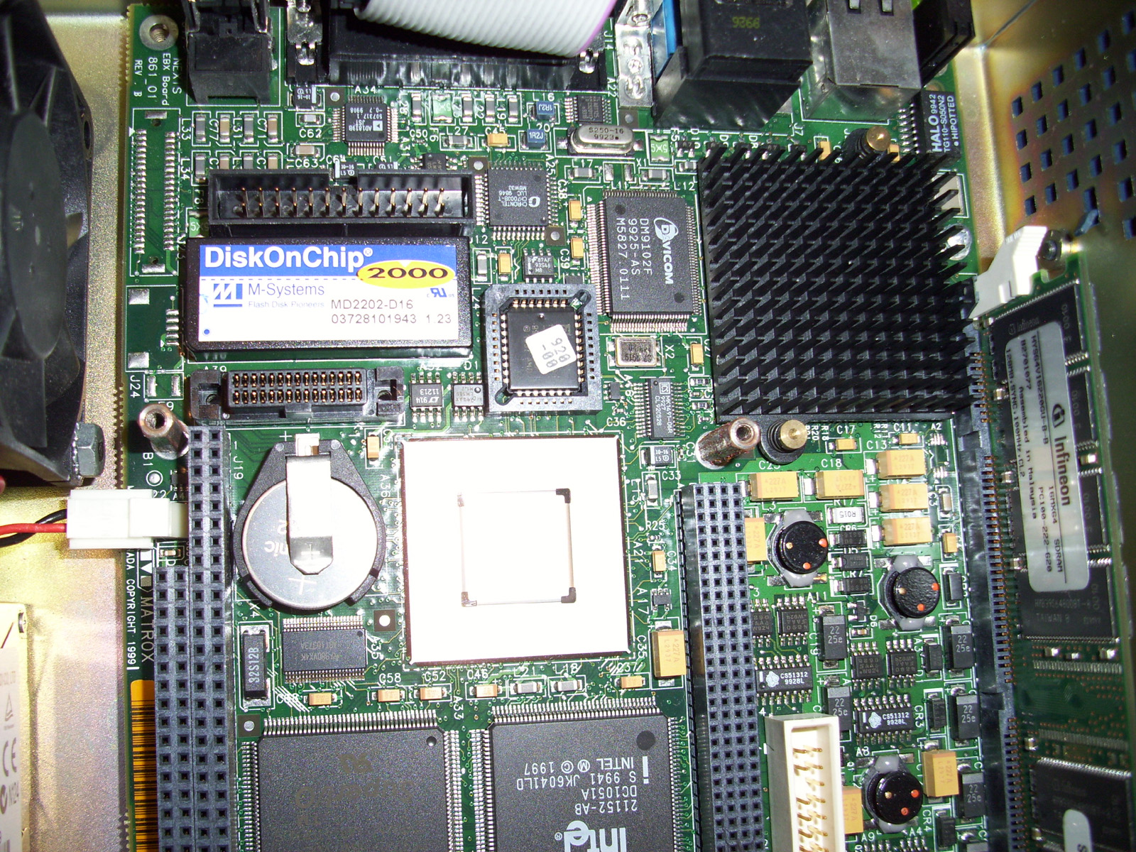
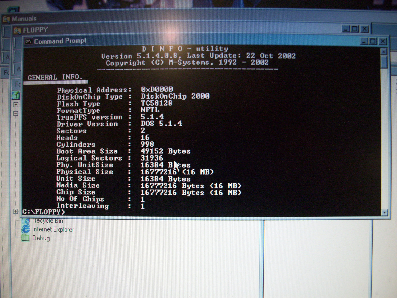
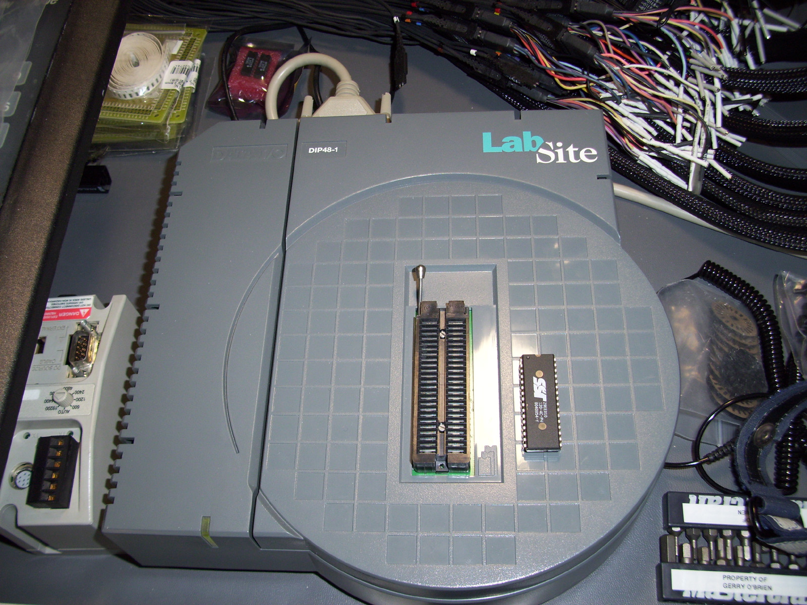
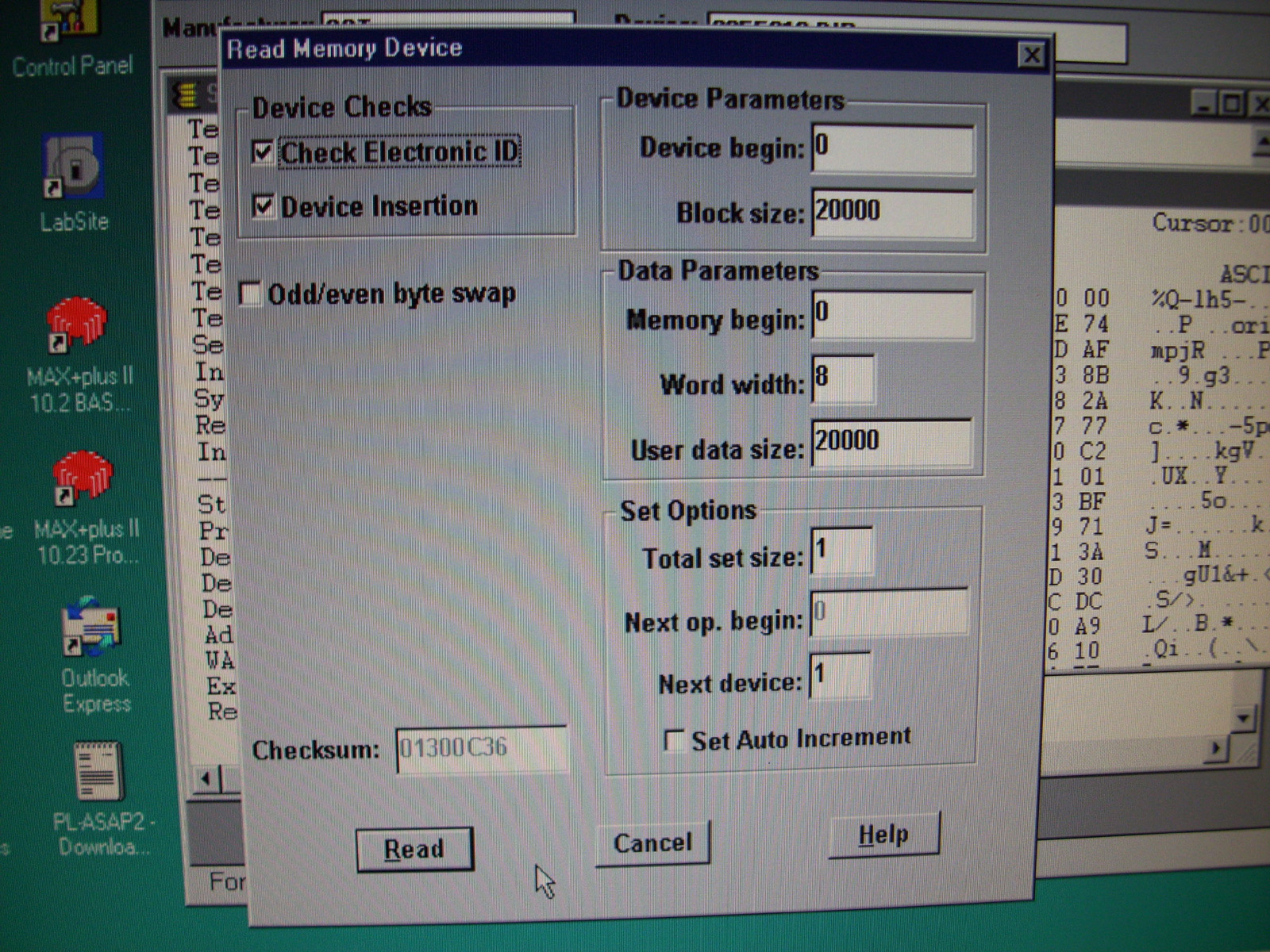
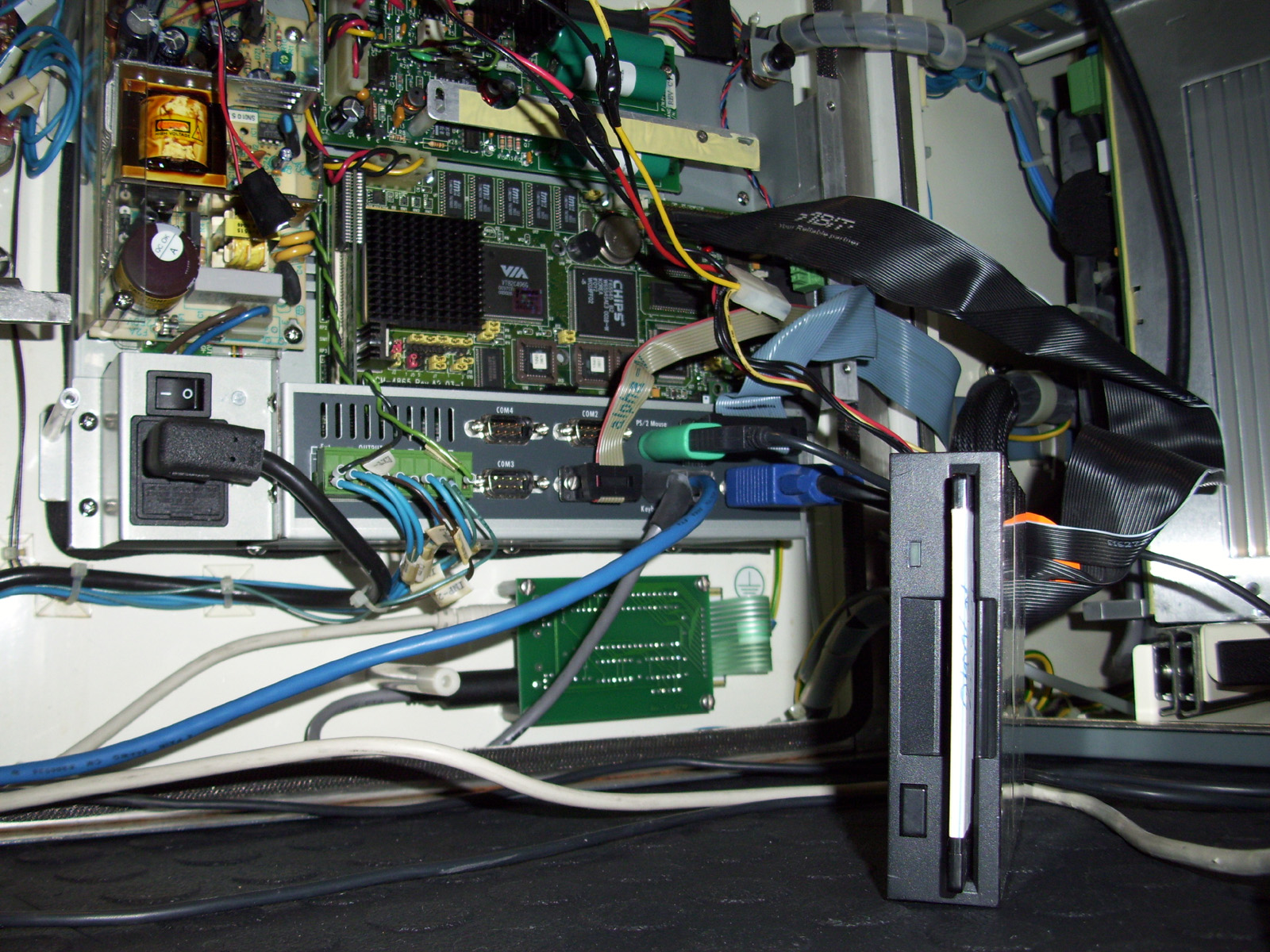
These SCM Modules shown below, slide into a track system enclosure frame, located in the middle of the controllers enclosure. Once locked in place, they Interface with the system circuit board that connects power and encoder feedback lines to the system. Apparently The SCM motor Controller modules function independently even if the PC and LCD Display assembly on the Controller Door are removed. This is apparently in case the PC needs to be serviced. The client can detach the Door from the controller and ship it off to be repaired. As long as no changes to the system need to be programed, the spindles will still perform their function. However, no feedback is available except for the LED indicators on the front of the SCM modules themselves. The SCM modules used in the INSIGHT PFS1-G & PFS2-G controllers, are Model# 99388019R08 with Firmware Rev. 99387847R5.5. (Which I have a copy of for Restoring purposes if need be.) I had to repair a few damaged cable assemblies on the SMC interface PCB as shown in the Image below. This was most likely from frequent trouble shooting and repeated opening and closing of the Controller door. The software on this unit was also corrupt and so I had to try and find a source of the software, which was close to impossible. I managed to find a matching Motherboard for sale on eBay that happened to be from one of these controllers. The lucky thing was that the motherboard still had the Software storage Chips attached. These chips were called "Disk-On-Chips" and were essentially the beginning of solid state drives, or SSD hard drives. I used an old industrial Micro PC computer I had, which was equipped with a "Disk-On-Chip" socket. I made a duplicate (.img) Image file of the chip for archival purposes and then re-programed the image onto the units Disk-On-Chip. I also backed-up the SST EEPROM chip that stores additional Firmware for the system.
For specifics on programming the M-SYSTEMS "DiskOnChip" Flash memory devices, please visit my devoted page at the link below: M-SYSTEMS D.O.C. Programmers "Disk On Chip Programming"
Once I reprogrammed both Chips... I was then back in business and the Controller software booted up in the Factory default mode just fine. The controller Passwords were also in their default mode for levels 1-4. (1111, 2222, 3333, 4444) Once the software was up and running I decided to install a Floppy drive and make a Backup copy of all the Files on the C:Drive just as a secondary precaution. After investigating... I discovered that the Main Program for the Insight Controller is a DOS based program that is stored in a folder entitled "C:\TWISTER\". Pretty creative Software Engineers. Hehhe!! : ) I had to manually activate the A:\ drive in the BIOS menu and then reboot. I also interfaced a Keyboard and external VGA monitor to make things a little easier to work with. It's a real pain in the ass... constantly having to open and close the Controller Door to look at the Units LCD screen. Using the extra VGA monitor was much less of a hassle when having to pick and probe. So I have made a complete Backup of the Ingersoll Rand INSIGHT PFS2-G controller Software. A.K.A. "TWISTER" which I have in .ZIP format and also in the DISK-ON-CHIP image file format. I have also acquired various Drivers and BIOS Chip Images for the Advantech Motherboard, and Firmware files for updating the SCM's (SPINDLE CONTROL MODULE) to Version R5.5. So if anyone is in need of these, please feel free to contact me through my "CONTACT" page.
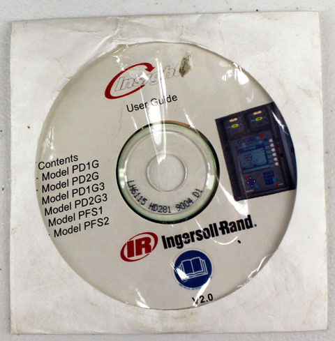
Interactive User's Manual for the INSIGHT PFS1-G, PFS2-G and INSIGHT IC Controllers I also have a few User manuals and other documentation for these Insight Controller units, and have used them to Program and Troubleshoot this system back into working order. Shown further below is a Link to a CD IMAGE file (.IMG) that you can download and then Burn to CD/DVD. This Image file is for a Web based Interactive User's Manual for the Ingersoll-Rand INSIGHT PFS1-G, PFS2-G and INSIGHT IC Controllers. Once you run the CD on your computer and the Product Selection Screen is loaded in your web browser, select the link "INSIGHT 1 & 2 Spindles" for the PFS1-G and PFS2-G controllers. Or you can select link "INSIGHT IC" for the PD1G, PD2G, PD1G3 & PD2G3 Insight Controllers.
Ingersoll-Rand_Insight_IC_Series_UserGuides_IMG_CD-IMAGE.zip
A Few additional INSIGHT Controller related manuals that may help you out as well. Ingersoll-Rand_Insight_IC_Series_UserGuides.pdf INSIGHT_IC_Operations_Manual_11-EN.pdf FTM308_Insight_PD_ICG_Advanced_Programming_BOOK.pdf
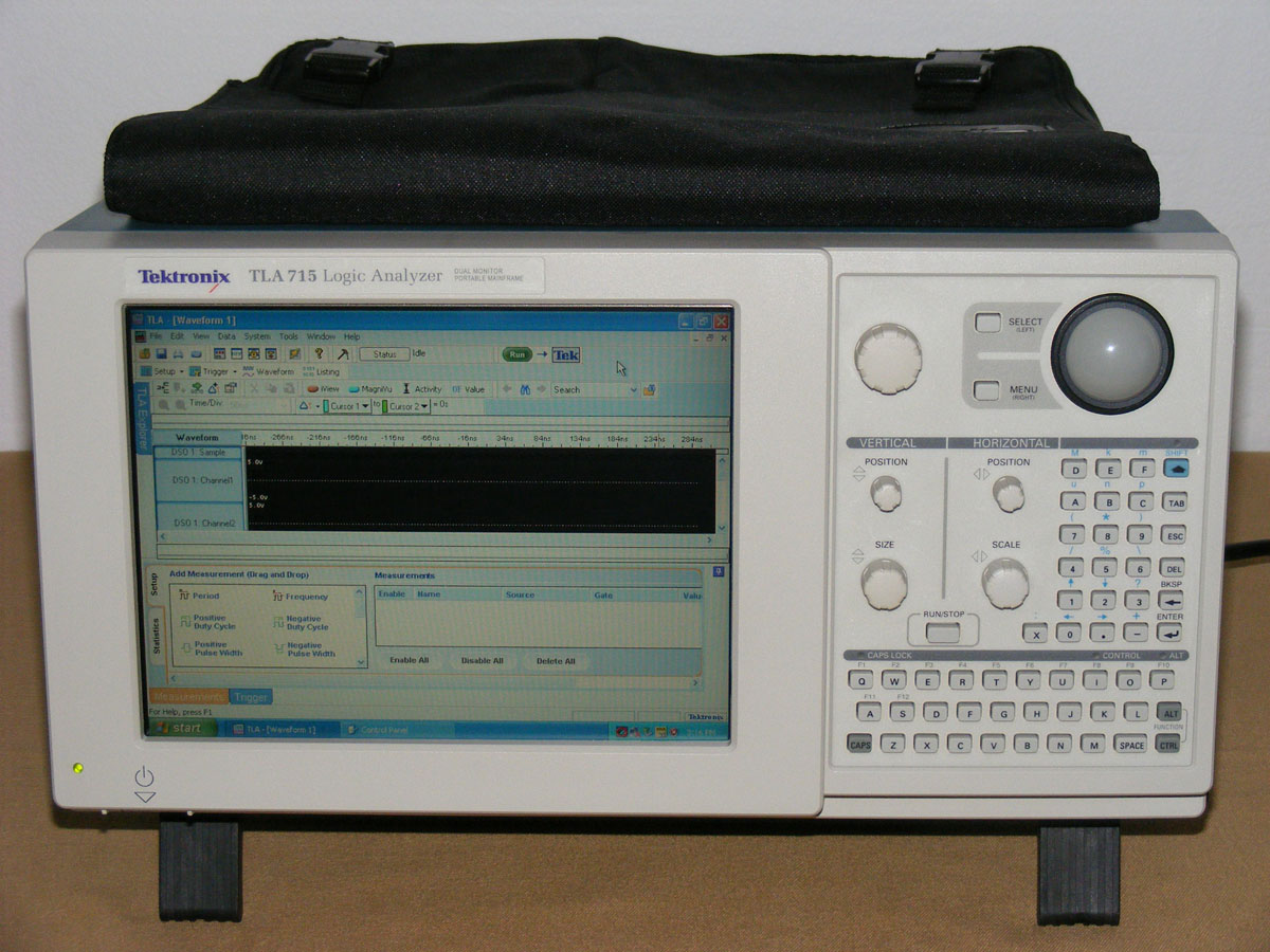
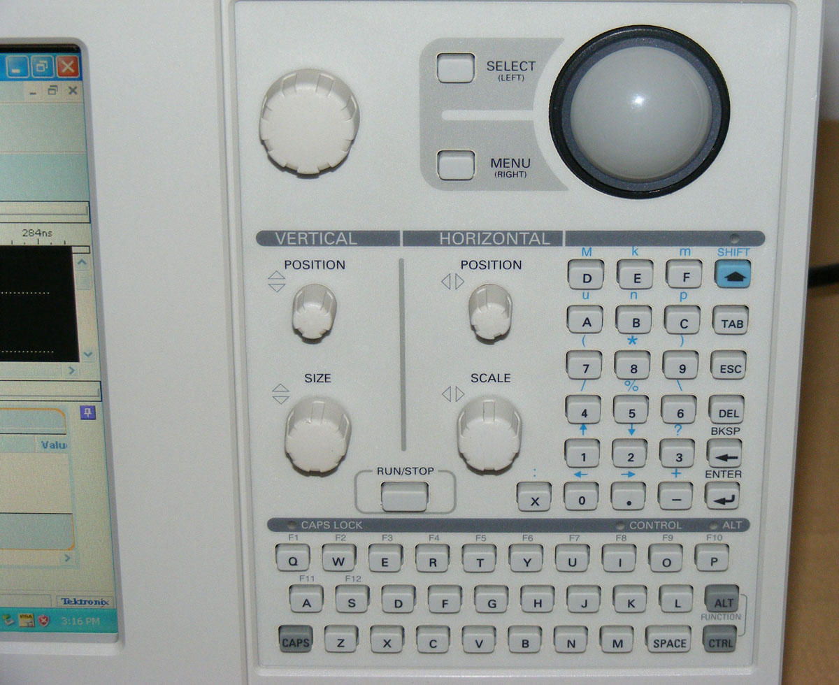
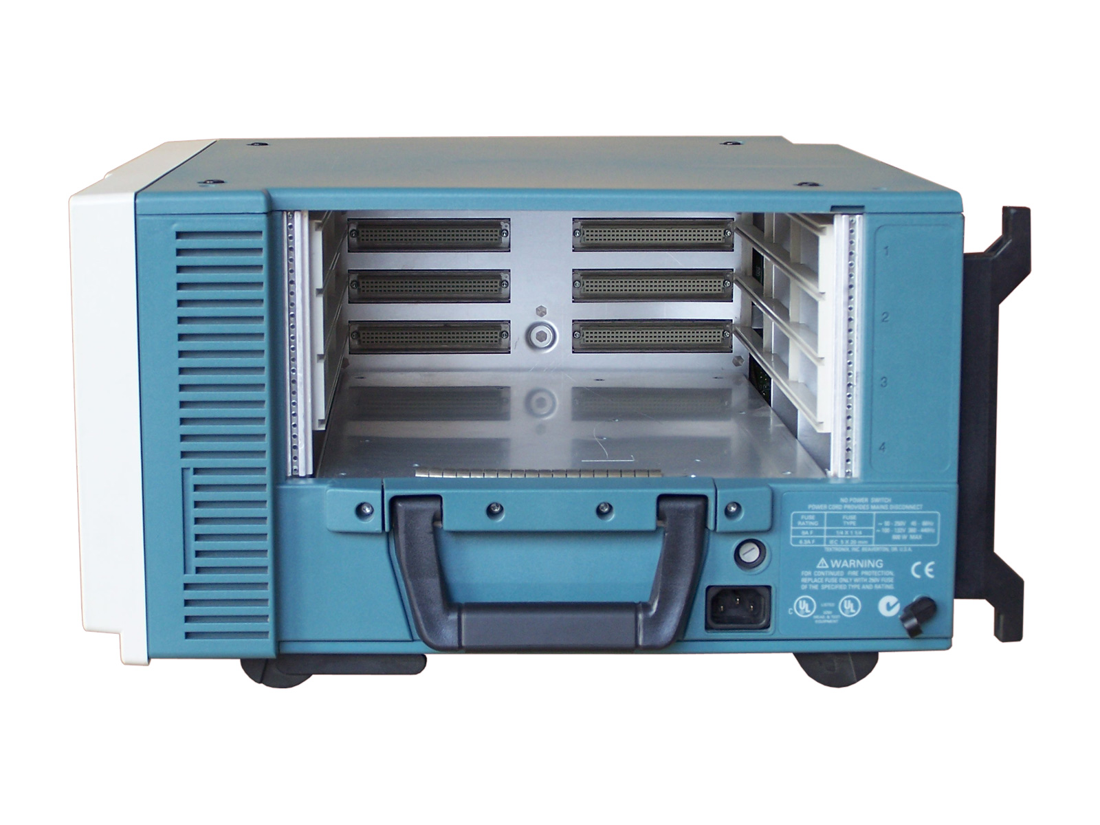
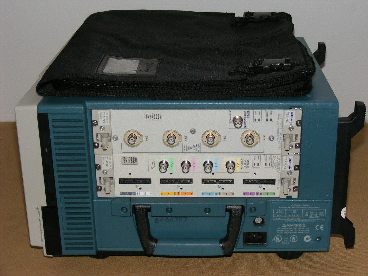
Shown Below are some shots of the TEKTRONIX TLA715 Model Logic Analyzer portable Mainframe.
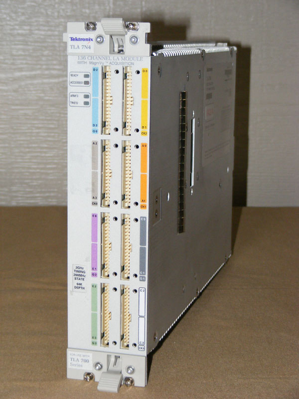
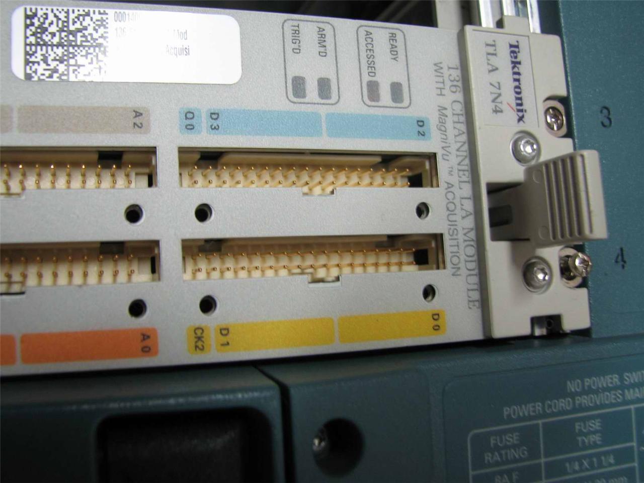
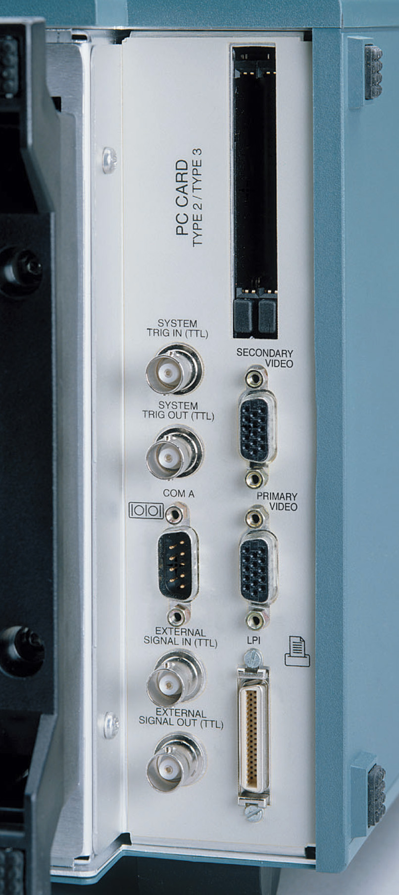
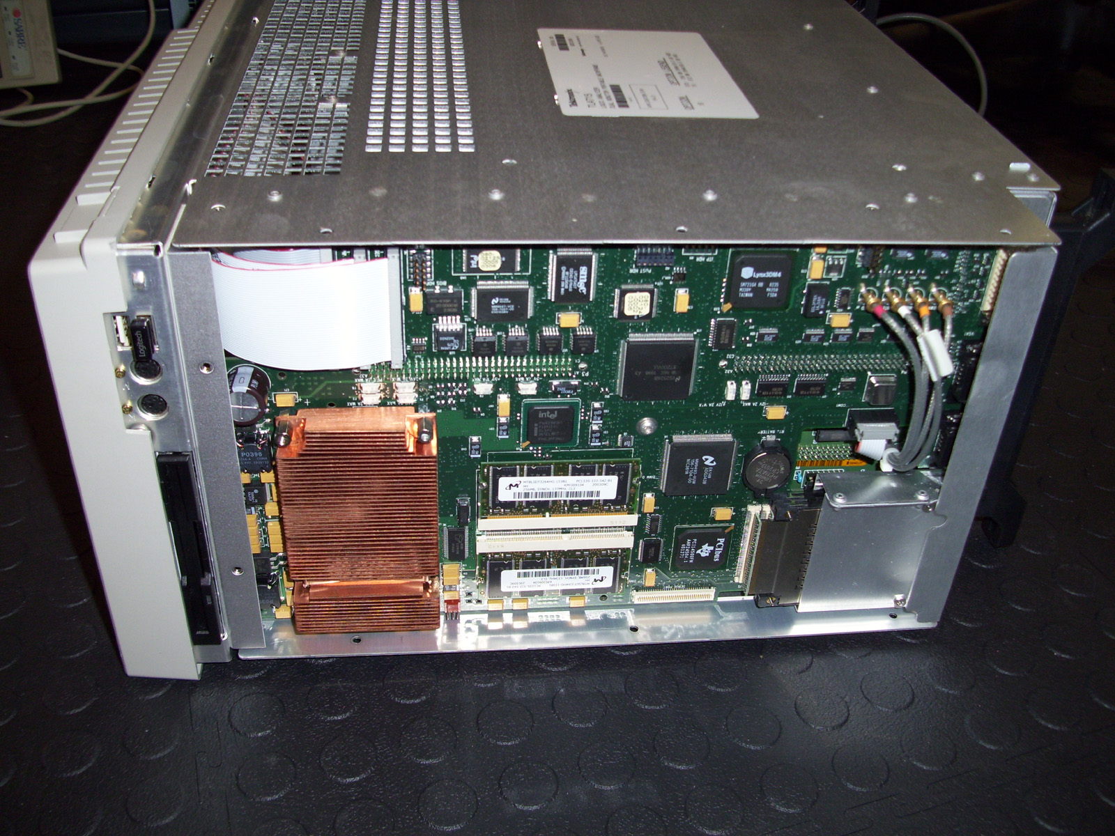
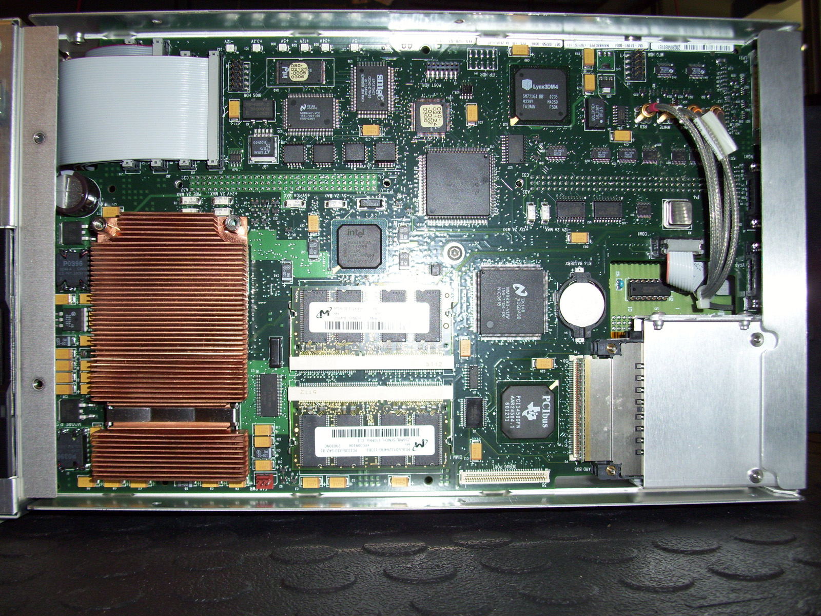
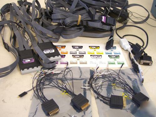
As you can see the TLA715 mainframe can accommodate (x2) standard interfacing Modules. It also has Rear ports for the Computer motherboard (Controller Board). (x2) PCMCIA CARD slots, (x2) VGA monitor ports, RS-232 port, LPT printer port, and External Trigger BNC connectors as well. The TLA715 Analyzer has its own Custom made Computer Motherboard AKA (Controller Board). This is the heart of the analyzer and runs Windows 98, 2000 or XP. I have Windows 2000 running on my unit and am using the Dual VGA monitor ports to interface two external LCD monitors running at 1280 x 1024 pixel resolution each with 256 colors. I had tried to add additional Monitors using PCMCIA to VGA adapters, however they were incompatible with the TEK Custom Motherboard in this system. Regardless, having two external Monitors for viewing is satisfactory. When the system is setup in the External VGA mode, the onboard LCD screen on the mainframe itself is disabled. This setup works best for me, as I am running the unit in a Lab setting and not in the field. As shown in the center image below, is the Tektronix P6417 16-Channel Logic analyzer Probes that are used with the TLA7N4 Modules.
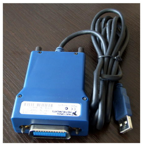
Also shown above on the Far Right, are a series of the P6418 LA Probes. I also recently discovered that this particular Mainframe has the ability to communicate with other various Tektronix hardware via the side USB port. Connecting a "GPIB to USB" adapter made by National Instruments. I can interface a Tektronix TDS3054B Oscilloscope to the Mainframe using a standard USB to USB cable; along with a BNC cable for connecting the External "TRIGGER" interface between the two units. This allows for some very coordinated testing and sharing of captured data.
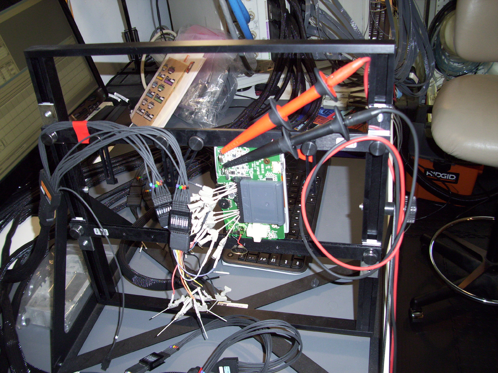
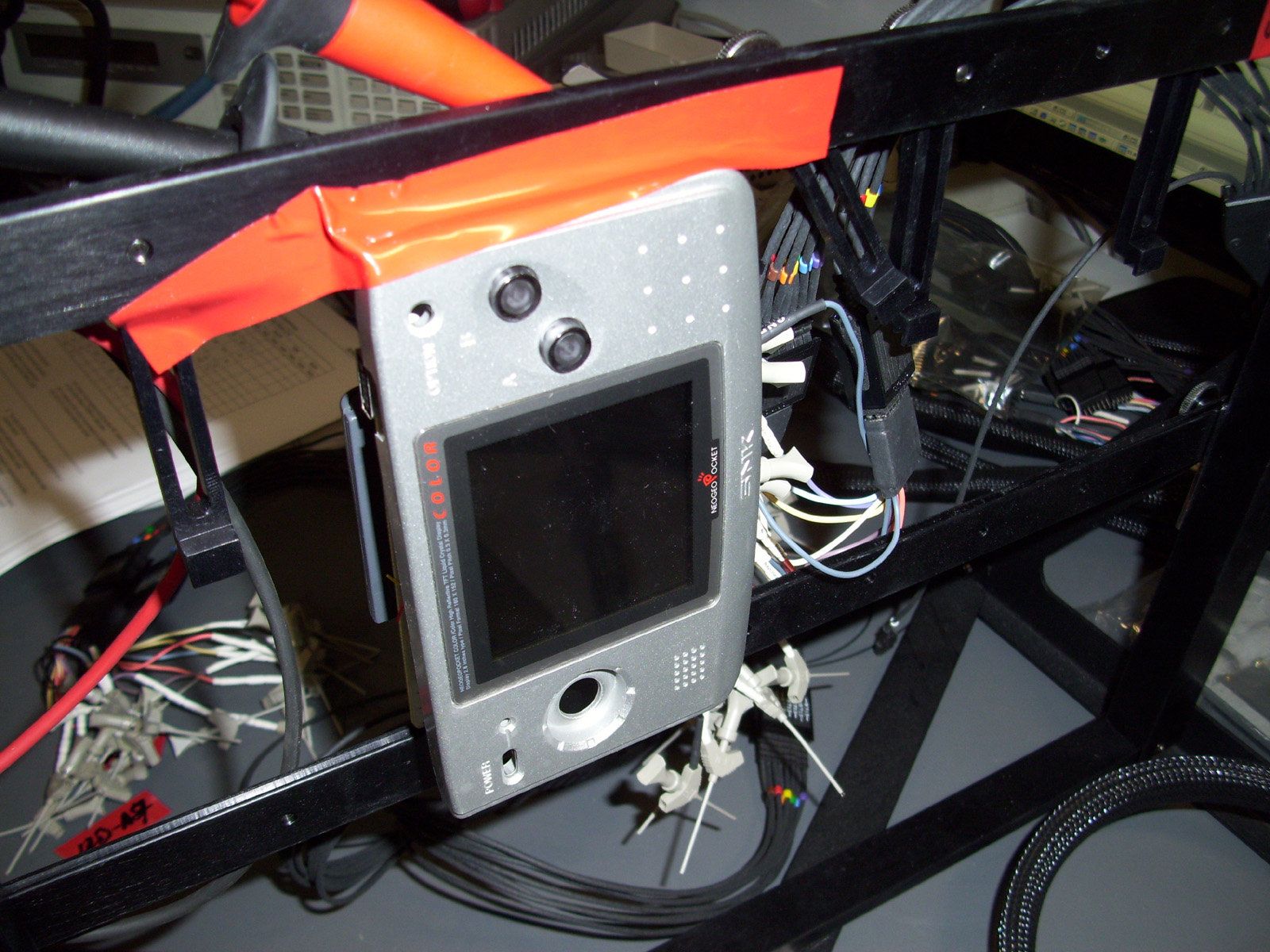
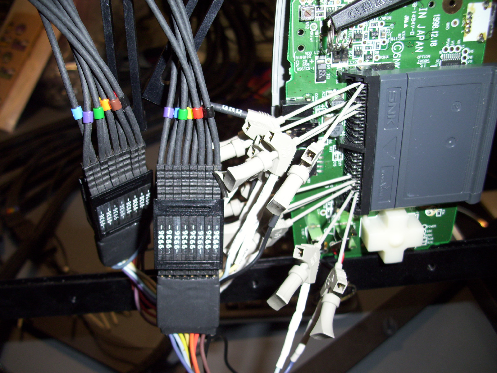
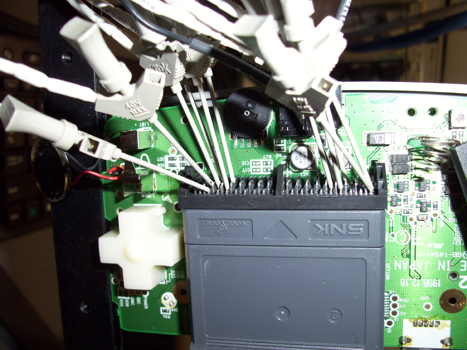
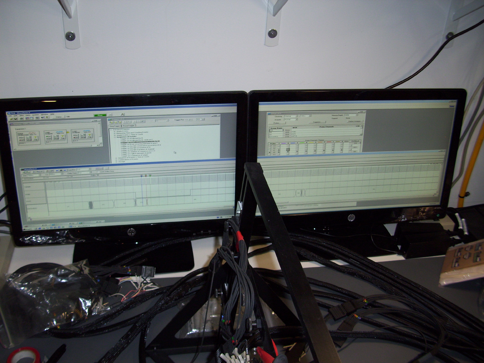
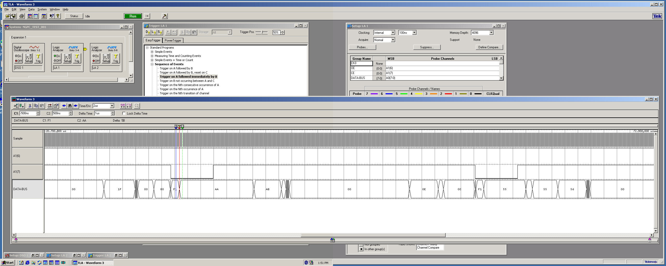
My Logic Analyzer running some tests on an NGPC handheld game console. Shown below is the time I used my Logic Analyzer to scan the Databus on an NGPC (NEO GEO POCKET COLOR) handheld video game unit. This was during my time working on a Flash-cartridge Prototype with Ed Mandy (AKA "Flavor"). Ed and I worked on this project for about a year and a half. Ed is now selling these Flashcarts as a Kit. Link is available on my Projects Page under "NGPC". As seen below, I interfaced to the various Mirco-controller control lines and its DATABUS for monitoring various Logic levels, and HEX control commands to verify proper functionality of the custom memory controller chip. Fun Stuff!! :)
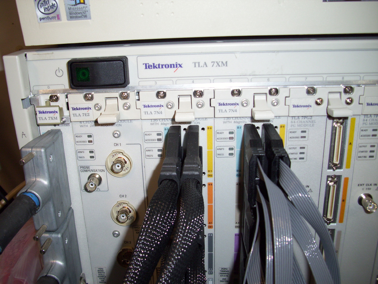
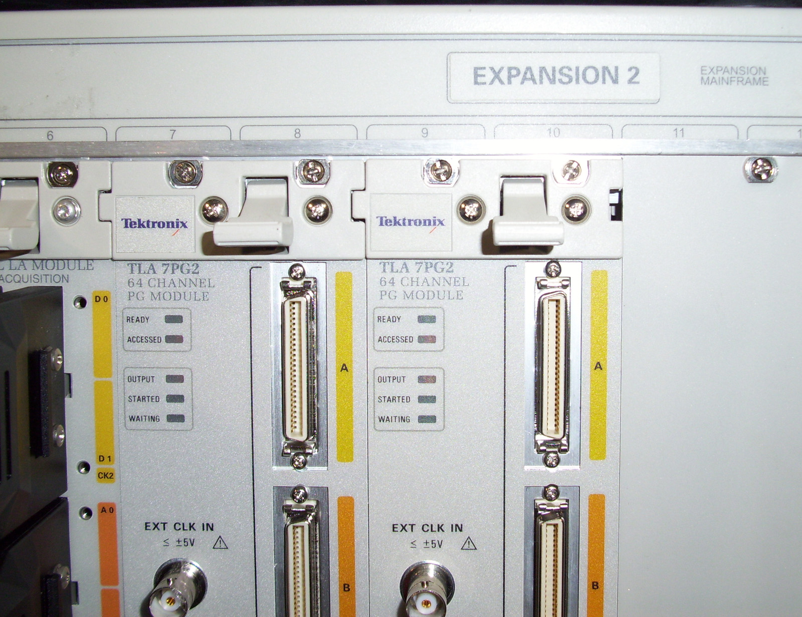
Recently repaired a Tektronix "TLA7PG2" Pulse waveform Generator Module.
I recently repaired a TLA7PG2 pulse waveform generator module for my Tektronix TLA715 Logic Analyzer portable mainframe. I was able to repair the unit due to the fact that I had one working module. There was an ALTERA MAX 7000 CPLD that was damaged and I was able to use the good module to duplicate the CPLD. (Luckily the Security-bit was not set) I duplicated the data to a new component for re-work.
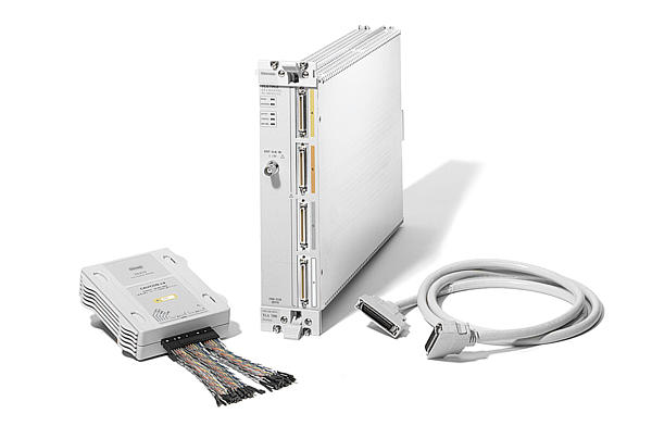
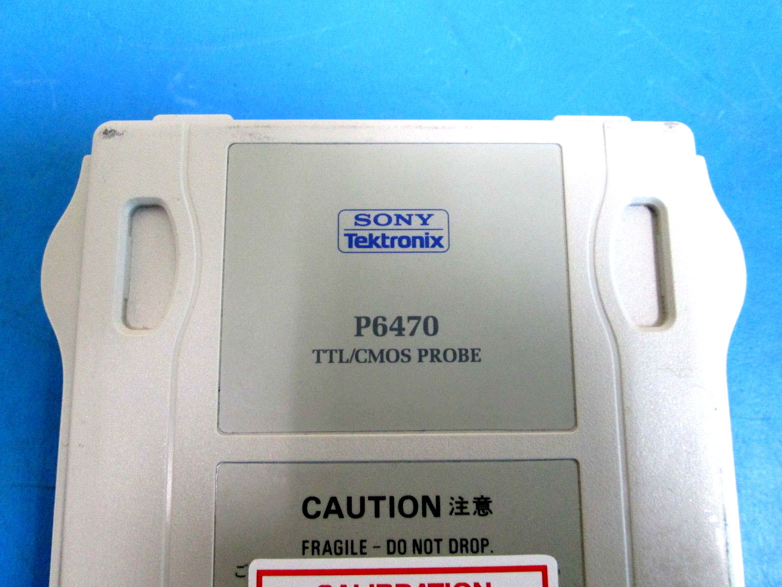
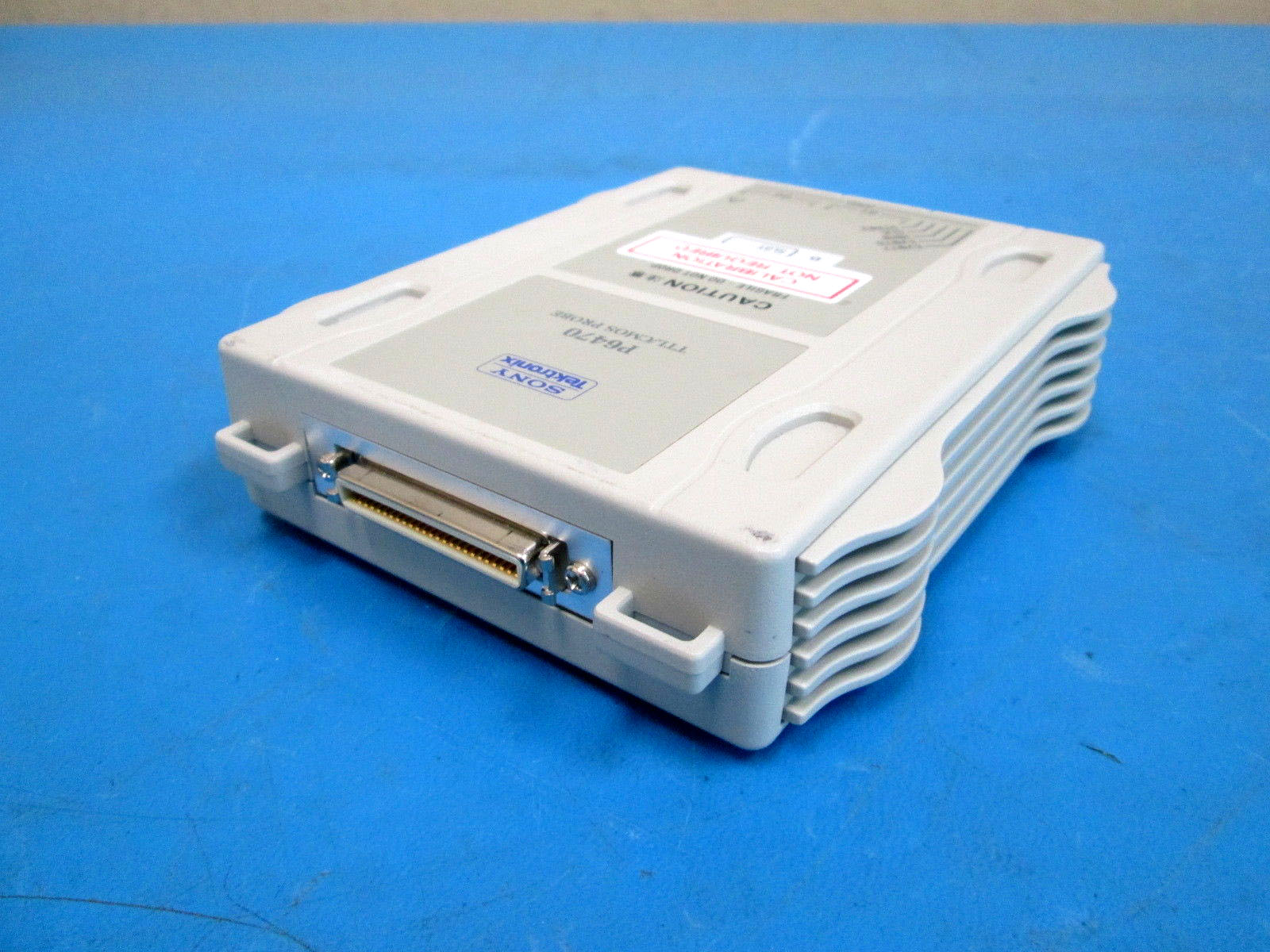
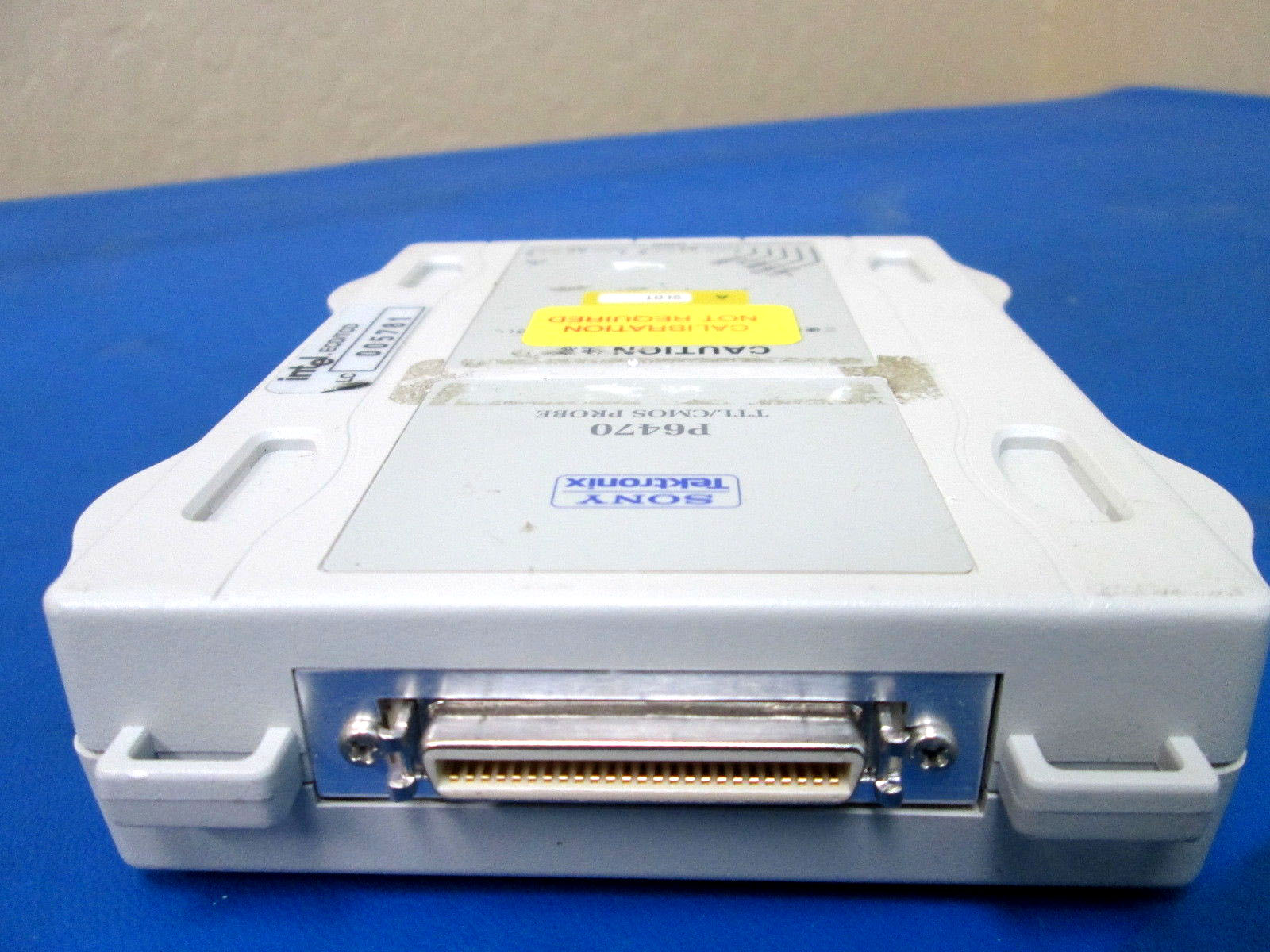
As you can see in the images above, I now have (x5) different modules inserted into my TLA Expansion Box that interfaces to my Tektronix TLA715 Logic Analyzer Portable Mainframe. I have the following Modules installed: - (x1) TLA7E2 (4ch Digital Oscilloscope) - (x2) TLA7N4 – with Option 7 installed (136 Channel Logic Analyzer Module) - (x2) TLA7PG2 (64 Channel Pulse Generator Module) with P6470 TTL Logic interfacing PODs. With this setup, using different Triggers and various Waveform Patterns, I’ll be able to execute some sophisticated Test Benches on different CPLD/ FPGA or Micro-controller projects I’m working on. I can then monitor the results on the Dual VGA Monitors that are interfaced to the LA Mainframe. Fantastic!!
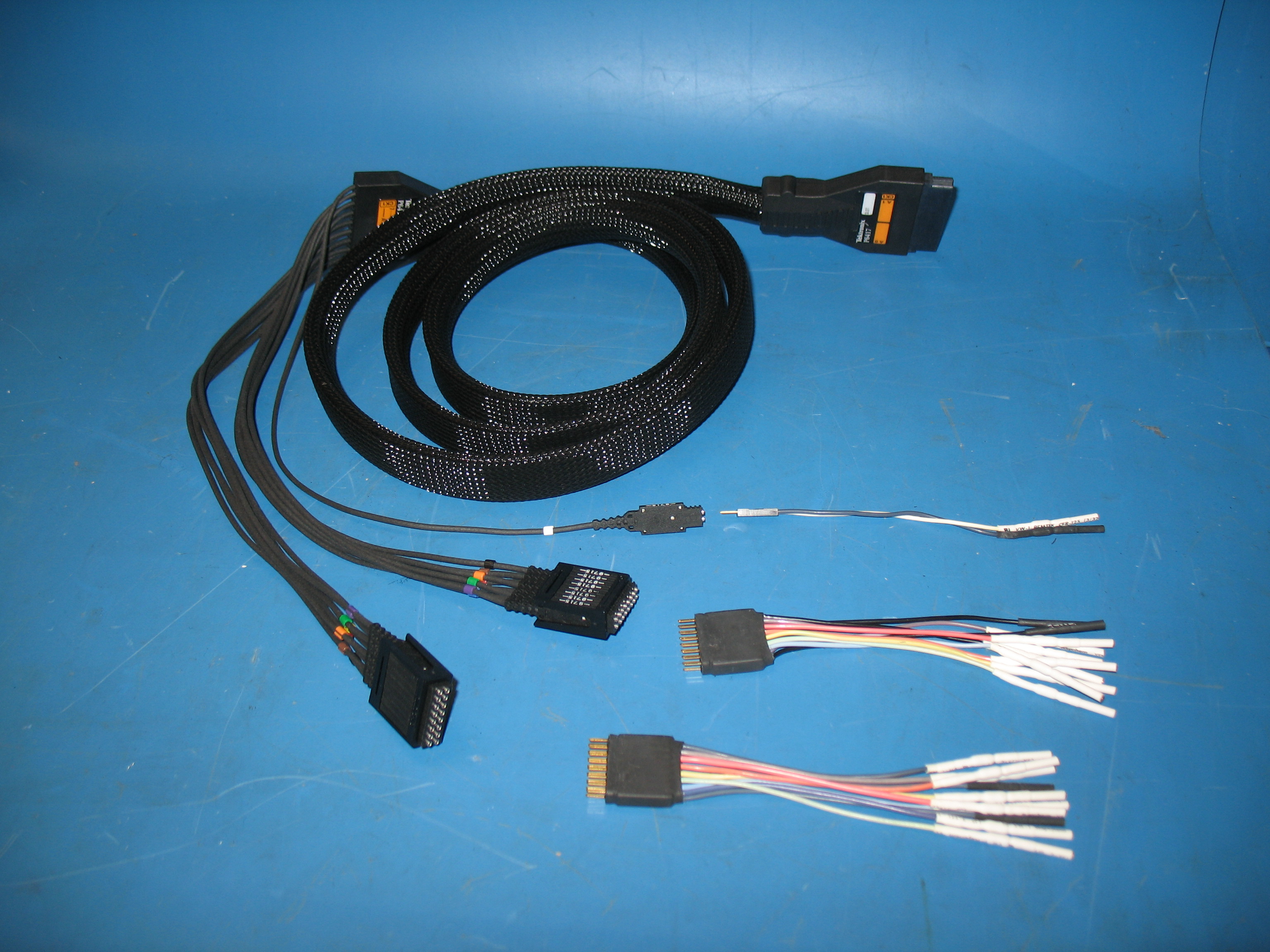
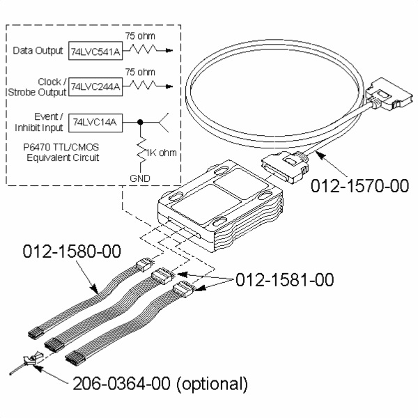
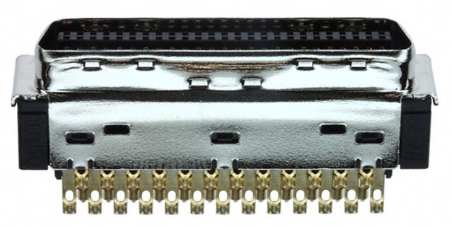
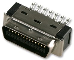
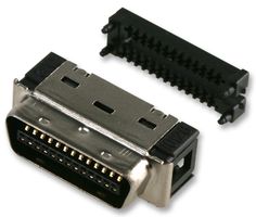
The Tektronix TLA7PG2 Custom "PROBE" Cable Below you can see the Tektronix issued “Probe cable”. This cable is a special, one of a kind custom made cable designed specifically for the Tektronix TLA7PG2. It is used to connect various PODs to the Pulse Generator Module.
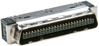
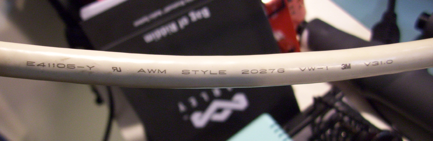
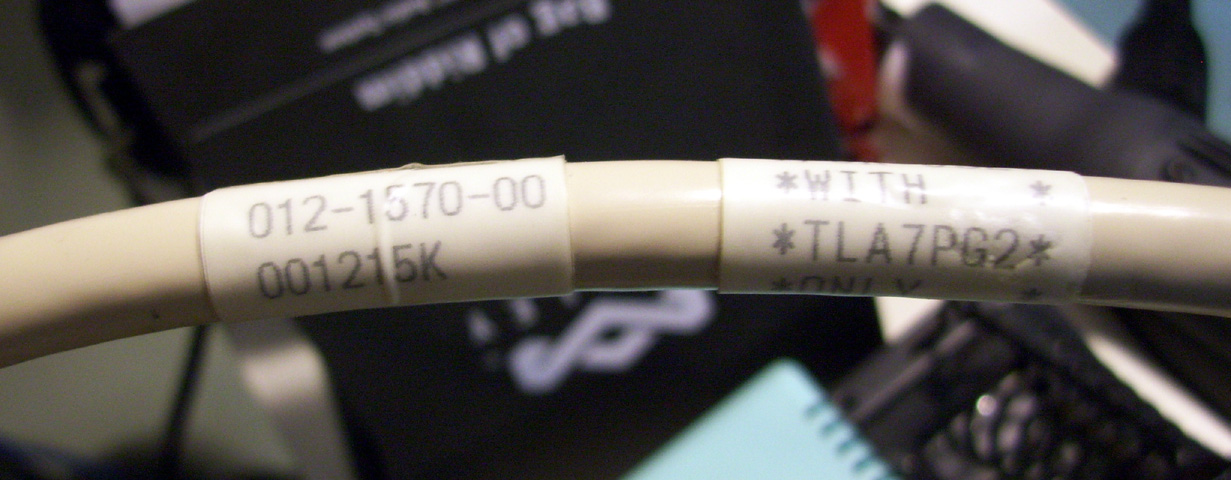
The cable has the Tektronix Part# 012-1570-00 as shown in the Image above. It is a 50-pin Male to Male “Mini-D Ribbon” connector cable. Also known as an “MDR” connectors. The cable itself uses a special shielded Twisted pair configuration to protect the differential signals from external Radio noise. In turn, these cables cost around $300 each directly from Tektronix, so some of you may wish to wire up your own cables. Be aware that this may be harder that it's worth. You must use the exact shielded cable type for proper functionality. The 50-Pin male connectors are often mistaken for an HD50-Pin SCSI cable connectors or "High Density" connectors. Most SCSI cables will only use Twisted Pair wiring and will not have the required shielding and it also uses a special Pin configuration. This is why Tektronix is so adamant for using TEKTRONIX issued cables only. ******* THIS CABLE IS NOT!! A SCSI CABLE. ******* This Mistaken Identity happens so often that it is even stated in the Modules User & Service Manuals, instructing the end users to not use SCSI cables.
Soldering up your own Tektronix "TLA7PG2" Probe Cables If you decide to build your own Probe cables for your TLA7PG2 module.... The info below will be helpful.
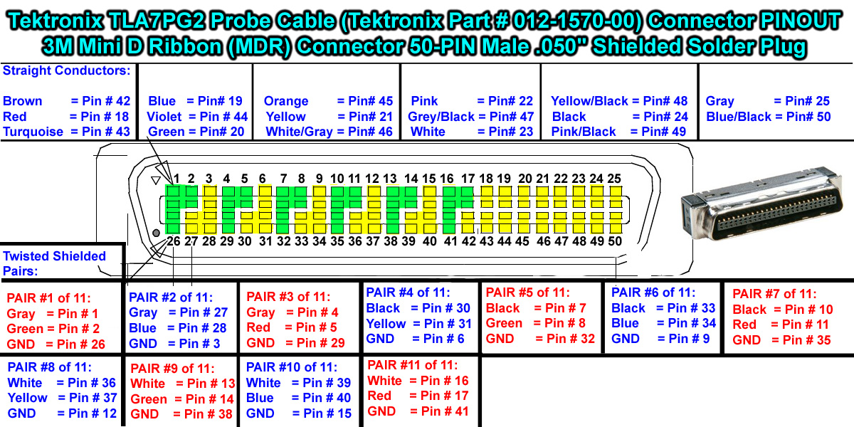
This Tektronix probe cable is a Custom designed cable made specifically for Tektronix and uses a special Wiring arrangement and Pin configuration. SEE THE MDR CONNECTOR PINOUT DIAGRAM BELOW:
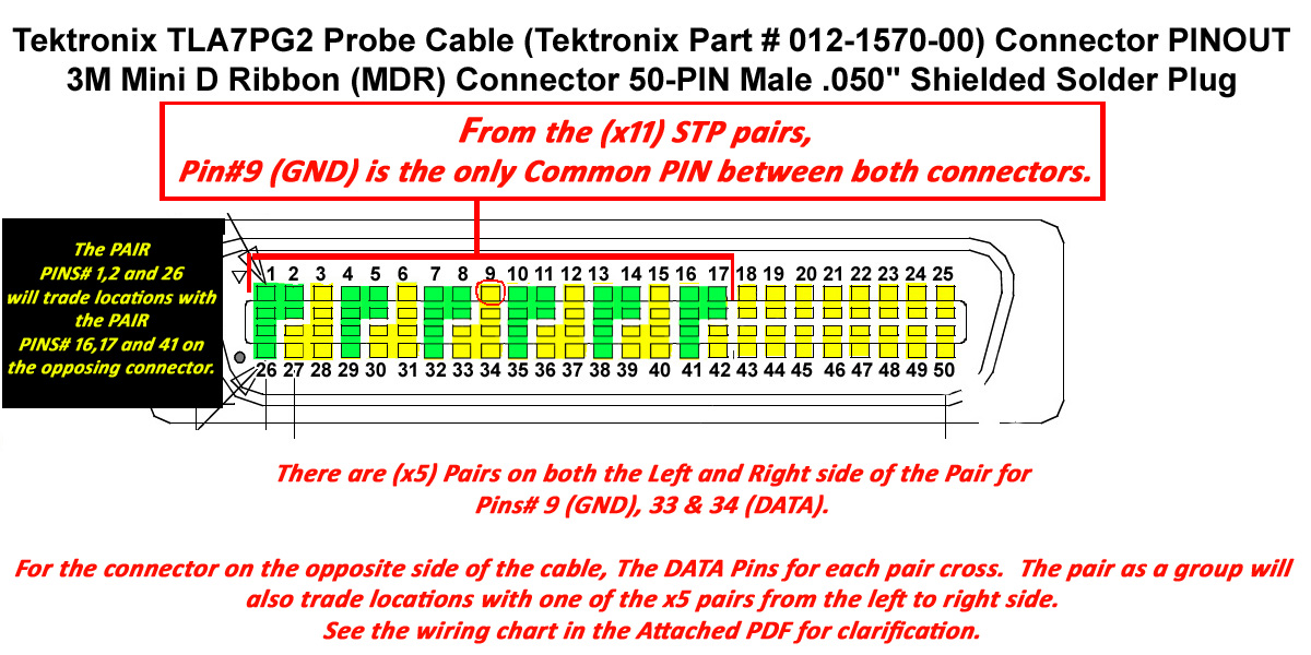
This cable is configured for (x11) Twisted Pairs that are individually Shielded with Foil shielding. Each pair includes a devoted Drain/Ground wire. There are also (x17) single conductors embedded in this cable. For a total of (x50) conductors. The (x17) straight conductors have a direct straight pass-through pin configuration. However, the (x11) TSP (Twisted Shielded Pairs) use a different pin configuration all together. See the Diagram below along with the attached PDF Pin-to-Pin wiring chart.
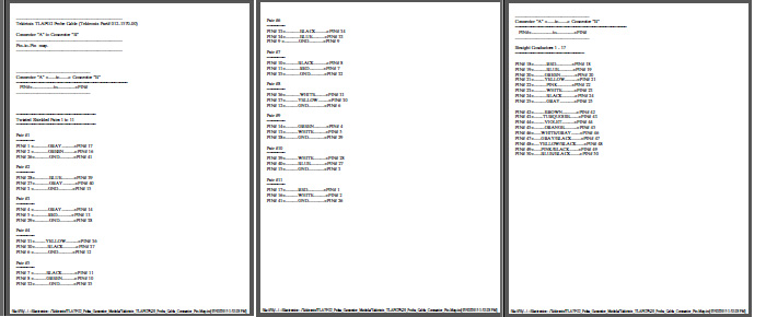
See the Pin-to-Pin wiring chart for clarification. (PDF Download Link Below) Tektronix_TLA7PG2 _Probe_Cable_Connector_Pin-Map.pdf
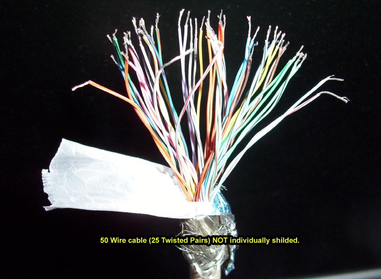
Be aware that many eBay vendors will list a so called 012-1570-00 substitute cable, selling for $150 each....when in fact the cable is simply a 25 Twisted pair SCSI cable without individual pair shielding and uses a different pin configuration entirely. This is False Advertising if you ask me. The cable is advertised as being a "shielded cable", but this is only because the shielding is on the main outer cable insulation and not on the individual twisted pairs. (x11) twisted pairs are required with an official Tektronix 012-1570-00 issued cable. See the images further below for a visual comparison: The Official Tektronix cable specifications used to make the 012-1570-00 is as follows:
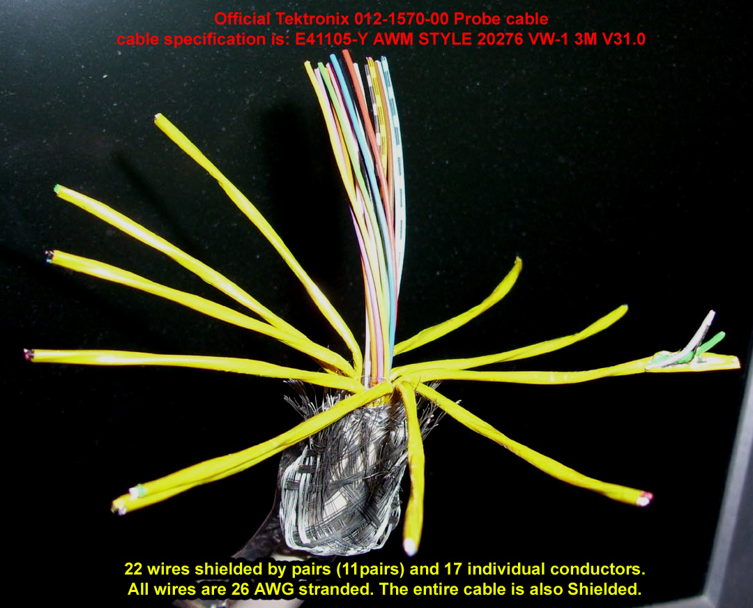
This is a Custom Cable made specifically for Tektronix and will be almost Impossible to find an exact match. E41105-Y AWM STYLE 20276 VW-1 3M V31.0 (x22) wires shielded by pairs (11pairs) each with a devoted Ground line and (x17) separate conductors 11 Pairs = (x22) conductors + (x11) Drain/Ground Lines + (x17) Straight Conductors = (x50) Conductors Total
TEKTRONIX will also label their cables with a Clear heatshrink indicating the Cable part number 012-1570-00 and that it is for use with the TEKTORNIX "TLA7PG2" ONLY. The Official Tektronix 012-1570-00 issued cable has (x11) Shielded twisted pairs, each with a devoted Drain GND line. These pairs are shown with the Yellow Foil shielding in the first Image below. The cable also has (x17) individual conductors for a total of (x50) wires.
Make sure that the cable you use is not a different configuration like a 25 Twisted Pair SCSI cable (2nd Image above) with Shielding on the exterior insulation only. This is not equivalent for the Tektronix 012-1570-00 cable. The shielding for the individual twisted pairs is Crucial for proper functionality when generating Differential signals. (When using the P6743 "LVDS" PODs). This particular type of cable is Custom made specifically for Tektronix and may be impossible to find. As an alternative you could make your own cable by finding a similar type of Multi-pair shielded cable like using Computer DVI cables.
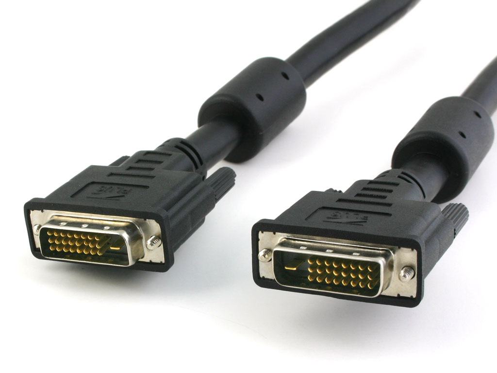
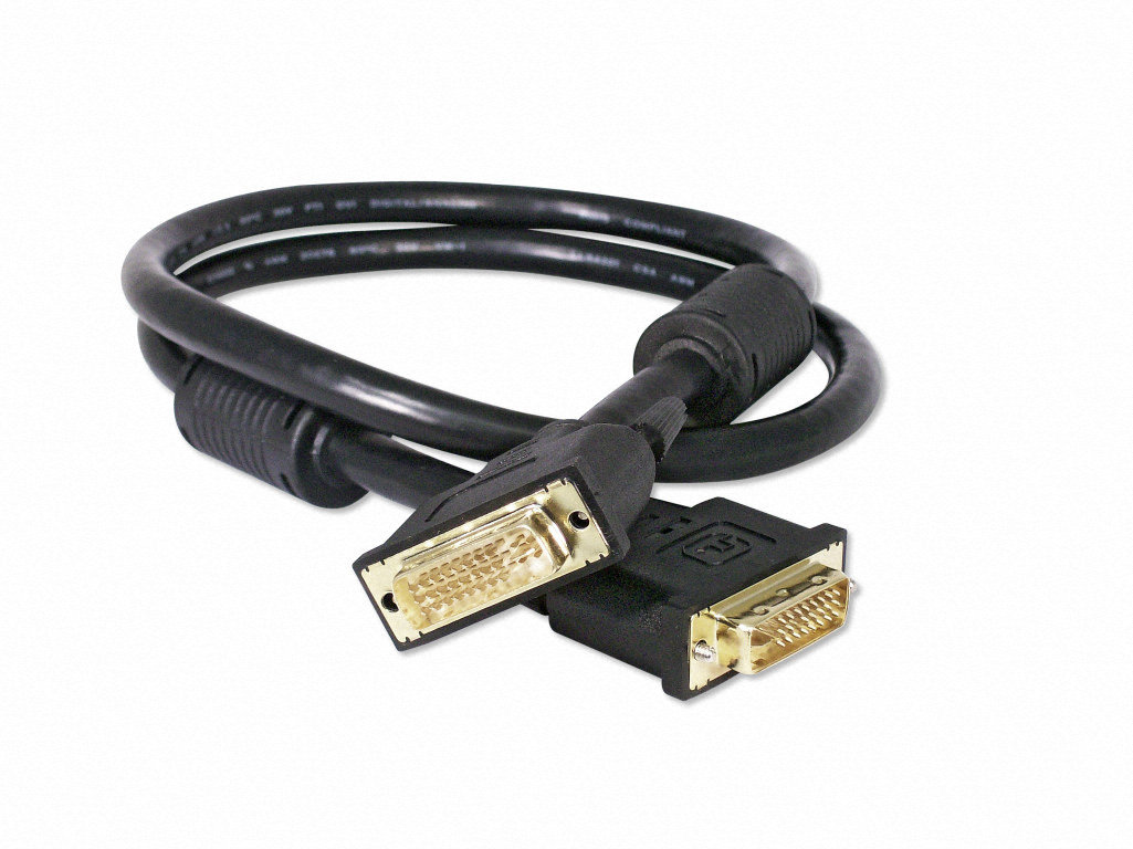
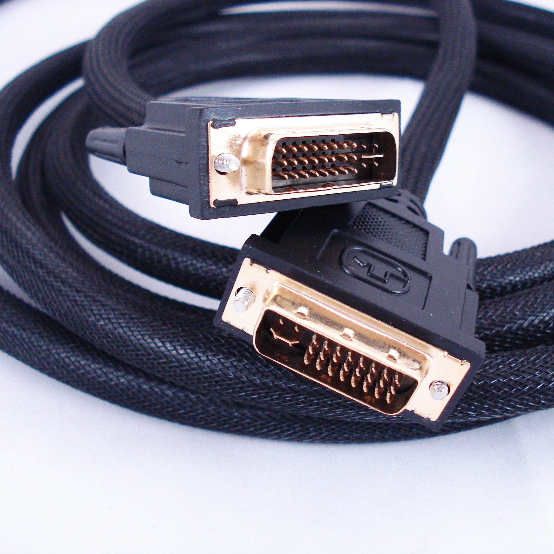
"Dual-Link" DVI Cables One perfect and super cheap alternative source for Shielded twisted pairs with a drain/GND wire, are Computer Monitor "DVI" cables as shown below.
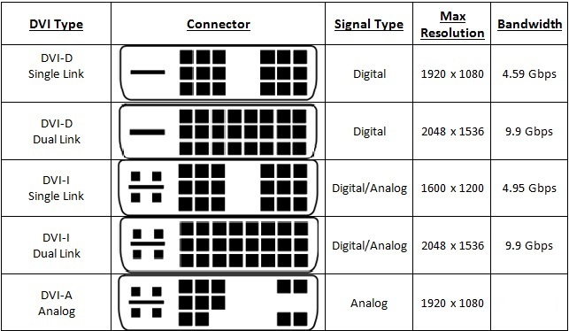
Computer LCD Monitor "Dual-Link" DVI cables. You can wrap a few of these together or strip out the shielded cables you need and heat shrink up your own. This is a cheaper alternative especially if you need more than 1 or 2 cables for your TLA7PG2 setup. The official cables New from Tektronix cost $300 a pop, and if you need like (x8) cables... you're looking at $2400 dollars before taxes and shipping fees...as you can see this adds up. The perfect DVI cable of choice are the "DUAL-LINK" DVI-D or DVI-I type. These types of DVI cables have (x6) Shielded twisted pairs each with GND/Drain wire, and also have (x4) straight through conductors. See the Diagrams below for more details:
The longer the DVI cable you can find, obviously this is better. So using a Dual-Link DVI extension cables is a perfect choice.
Cutting your cables to the same length as the official pod cables is a good idea. (5' Feet exactly.)
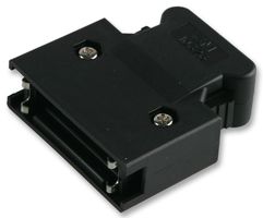
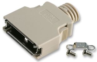
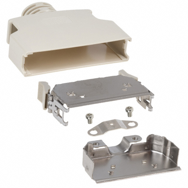
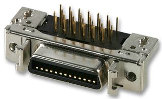
MDR Connector Backshells The company 3M manufactures both the male MDR Connector, and Connector Backshell with Quick release side Latches available for purchase so you can build your own cable. As shown below:
The Backshell is available in both a Plastic housing and also a Rubber Shielded housing. The Standard Plastic Backshell is 3M (Part# 10350-52F0-008). The Shielded Backshell is recommended and is 3M (Part# 10350-3210-000). Farnell Purchase Links shown Below: http://sg.element14.com/3m/10350-3210-000/backshell-mdr-50way-shielded/dp/9292993 http://sg.element14.com/jsp/search/productdetail.jsp?SKU=9292918&MER=BN-EN-PDP-9292918
You can also purchase the Male 3M 50-Pin Solder Plug Connectors (Part# 10150-3000PE) directly from Newark.com and Farnell/element14 at the links shown Below: http://www.newark.com/3m/10150-3000pe/mini-d-ribbon-conn-plug-50pos/dp/93K6327
The 50-Pin ribbon Cable version connector (Part# 10150-6000EL) is also available here:
If you by chance need the 50-Pin Female receptacle for these cables, the 3M part number is as follows: (Part# 10250-5212PL) Farnell link below for purchase:
Join my NEW Yahoo Group for Tektronix TECHs. Exchange files and talk with other Tektronix hardware owners. http://groups.yahoo.com/group/TekTronix_TECHs
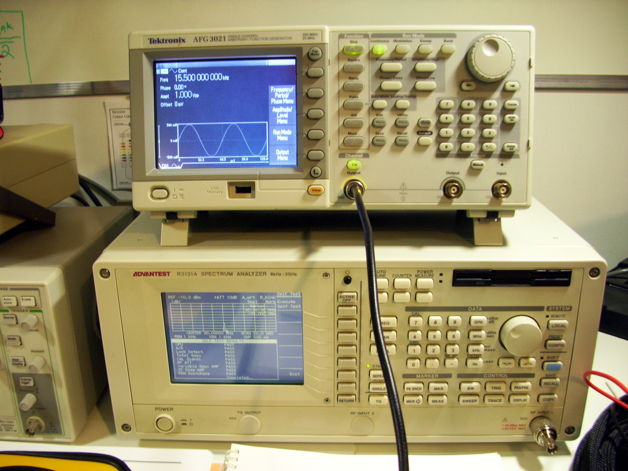
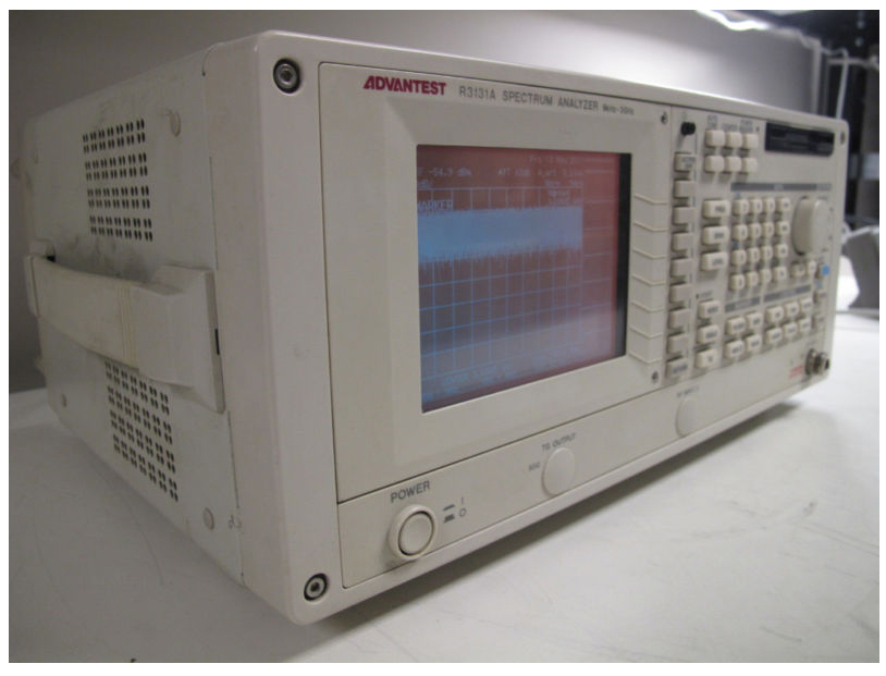
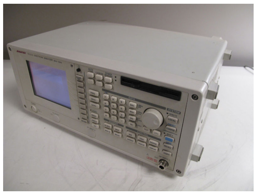
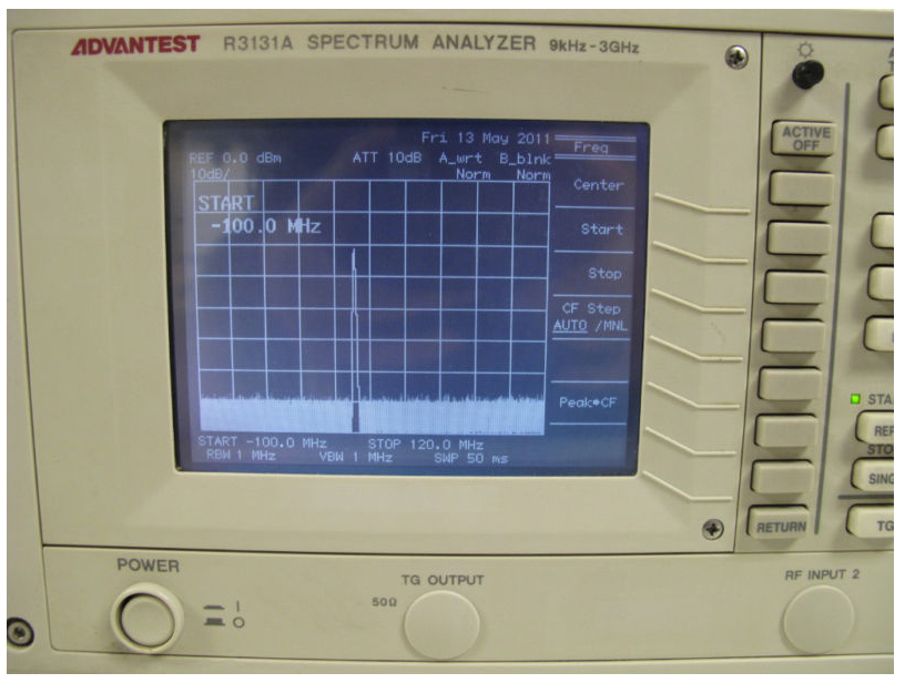
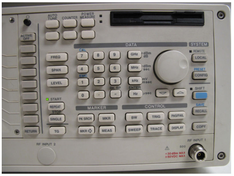
Shown Below are some shots of my Spectrum Analyzer. Advantest Model #R3131A 9Khz - 3Ghz Bandwidth
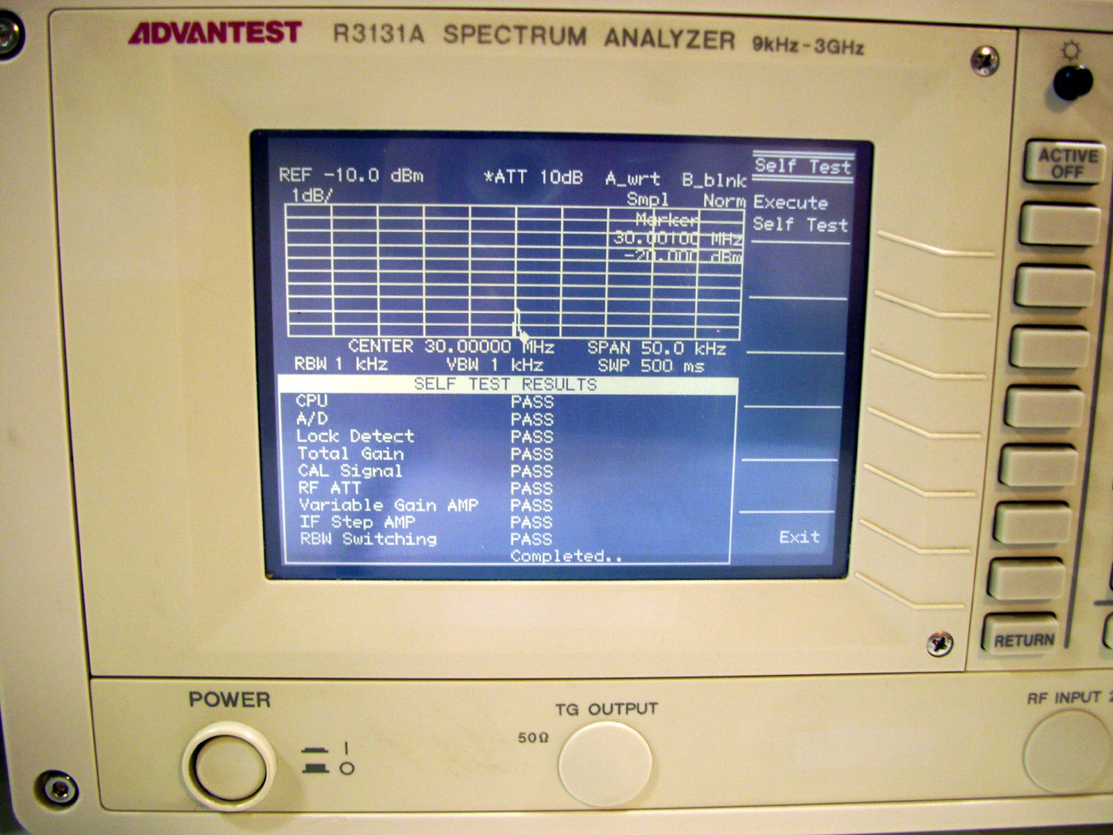
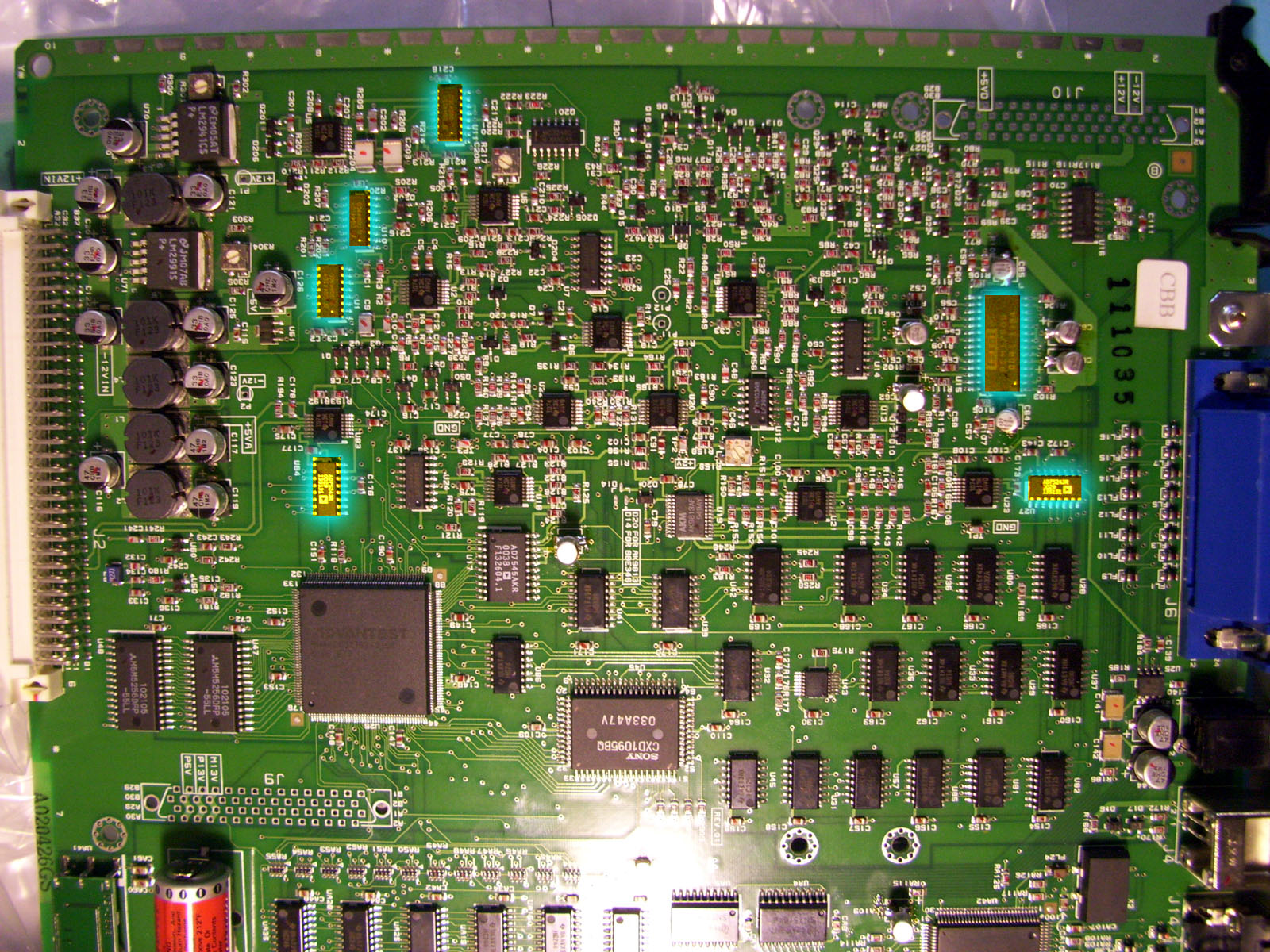
This unit has been under repair & calibration for a bit. However I just recently repaired it as you can see the Self-Test Passed all section (Photo Above). It's now working perfectly. The Self Test had failed with an error on the Analog to Digital converter Block. I managed to get the Advantest Maintenance Manual for this R3131A model, but there were no schematics included. So I replace most of the onboard electrolytic Capacitors to start. I also replaced the A/D chip that I managed to locate on the CPU/AD board Model# BLL-023465. However this didn't fix the problem. It turned out to be a series of CMOS Quad SPDT Switching IC's and a couple of DAC IC's also located on the main CPU/AD circuit board Model# BLL-023465.
After reading various datasheets and talking with other repair Techs, the CMOS SPDT switching IC's have a tendency to fail over time, so this is always a good step to replace them if there are any present in the system. This Unit will greatly assist me with my Analog and Telecom Labs for school, but also just with my own experiments. It should be a very good learning tool. Even though the unit is over 10 years old. It's still a Beauty. :) If you own an Advantest unit of your own, please join the "Advantest Instruments" Yahoo Group to help with your troubleshooting. It is a great resource for Manuals and also a great way to connect with other Advantest users. 
Click to join advantestinstrument
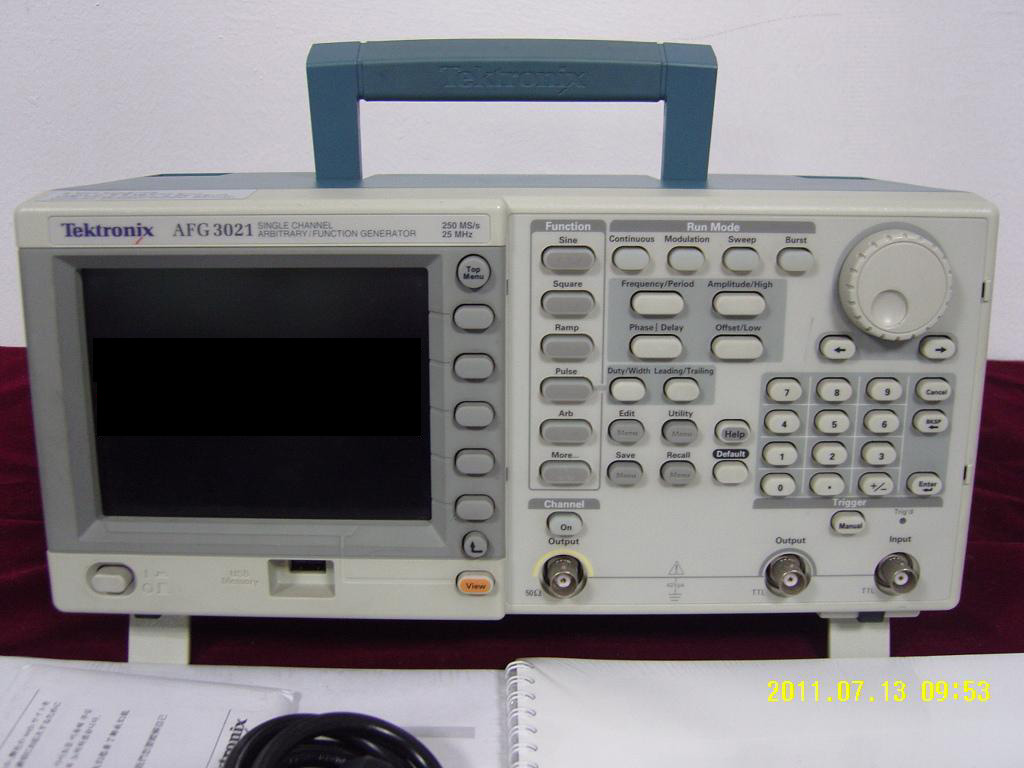
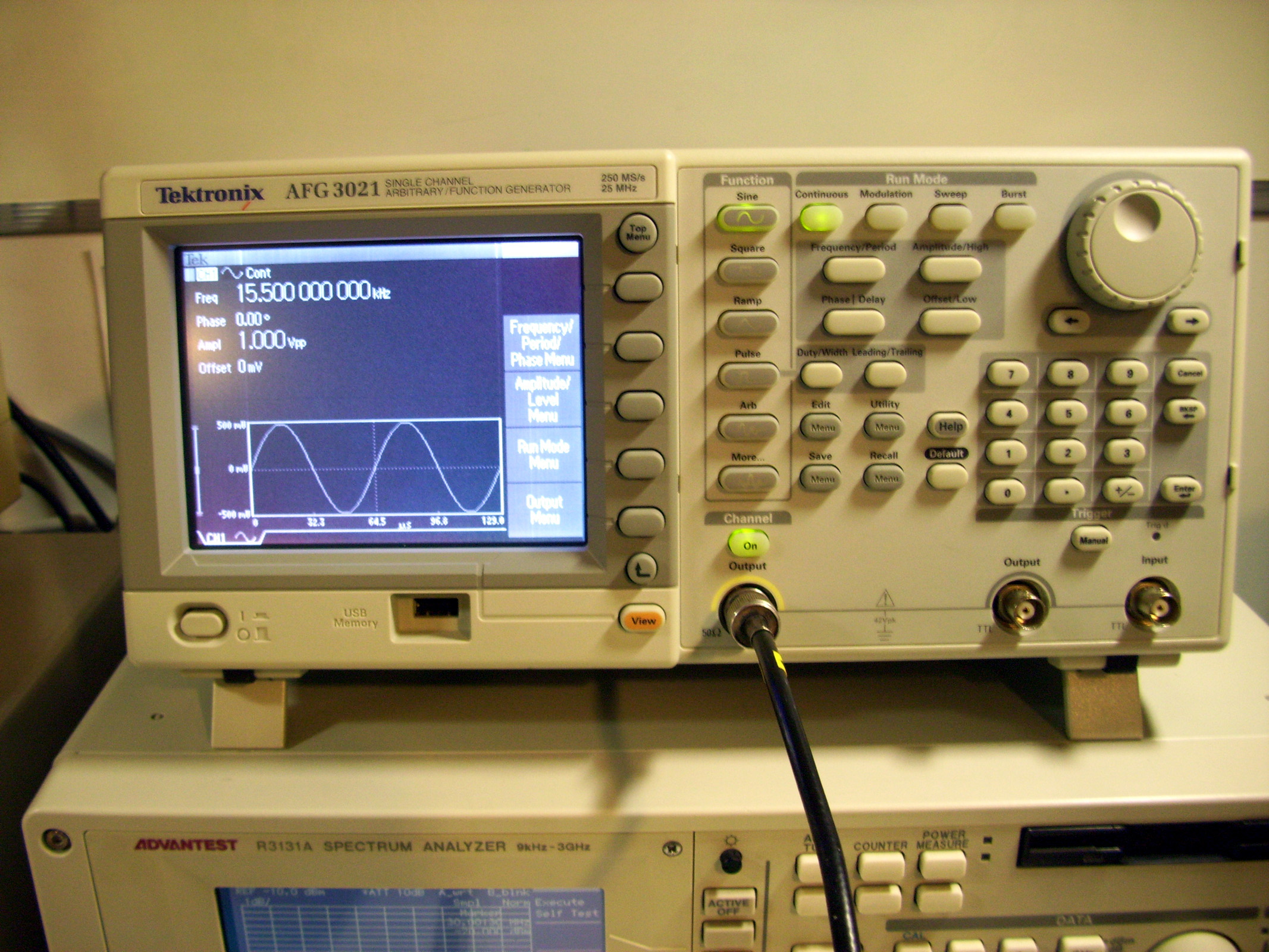
Shown Below are some shots of my Tektronix Function Generator. Tektronix Model #AFG3021 - 0.01 mHz - 25Mhz Bandwidth. I still have to fix this one though, so hopefully it won't take too long.......... ......................FIXED IT !!!
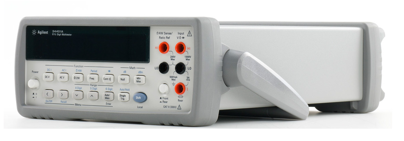
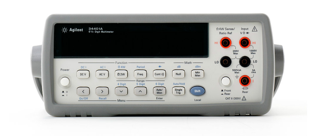
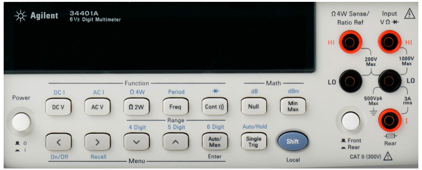
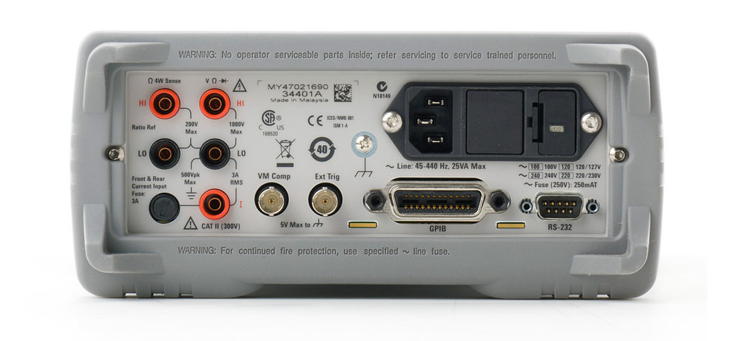
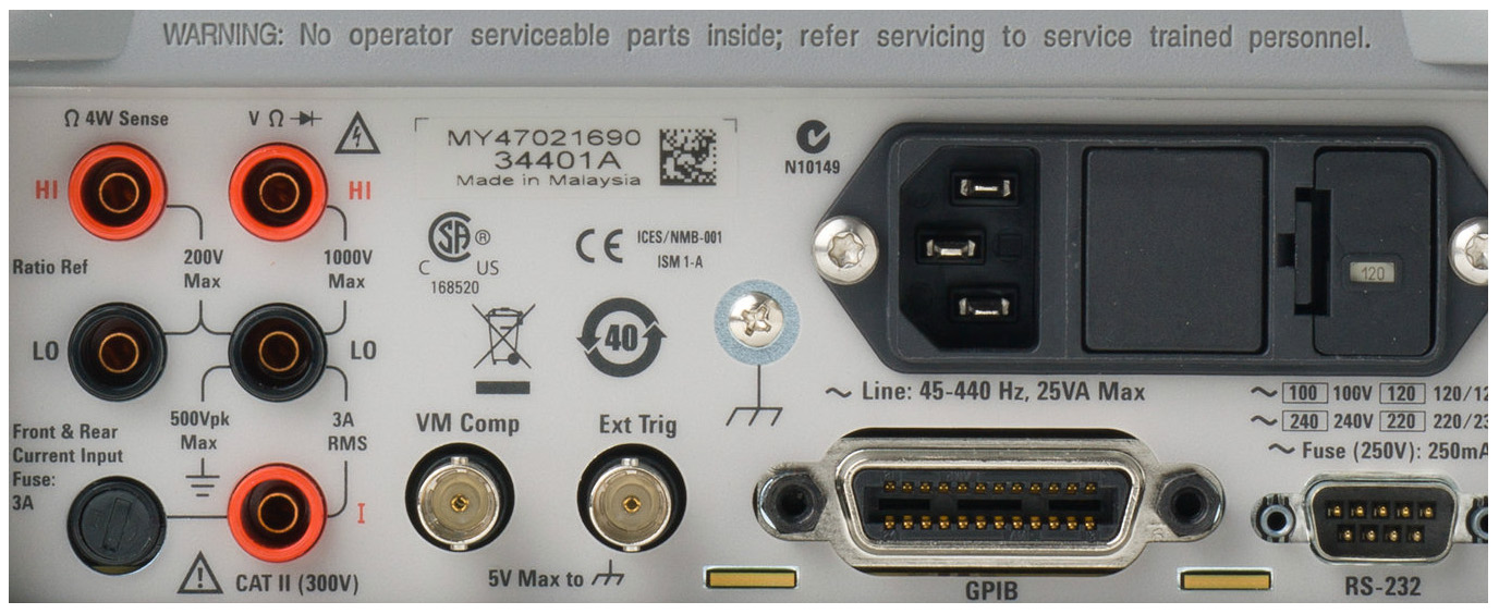
My HP/Agilent 34401A Multi-Meter. Nothing really to Say about this Unit except......SWEET!! :)
Check out this units Specs from its Datasheet: http://www.digital-circuitry.com/DOC/Datasheets/HP_Agilent_34401A_Datasheet.pdf
|
||
|
||


