|
Current Time:
|
|
|
|
|
-=Welcome to the VHDL Programming section=- -= VHDL =-
Learn how to Read and write a Logic design of your own using the Logic "Hardware Description Language" VHDL
Eventually... Time permitting....I will go through various Tutorials explaining how the VHDL language works. I will explain in detail what each part of a typical piece of code does, and how they function together. For now I will just go over some basic concepts of what The VHDL language is, and try to explain it in "Layman" terms for a better understanding of the fundamental concepts.
So to start: Well, you're reading this...... so that's a good sign.
VHDL IS VERY DIFFERENT THAN "C" or "C++" !!!!! Now, be aware... VHDL is a very different type of programming language compared to sequential based programming languages like C, C++ or Assembly code. So if you are a software programmer, or have programmed in "C" before.........ALWAYS REMEMBER! VHDL IS VERY DIFFERENT THAN "C" or "C++" !!!!!
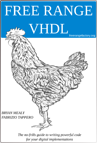
A similar type of code to VHDL is a language called “Verilog”. However, for now I recommend you go with VHDL. Start by reading this book called “FREE RANGE VHDL”. It’s free online:
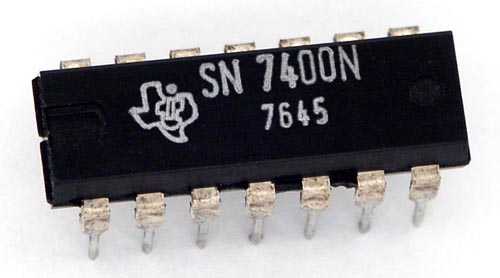
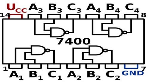
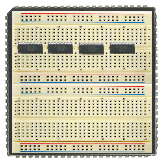
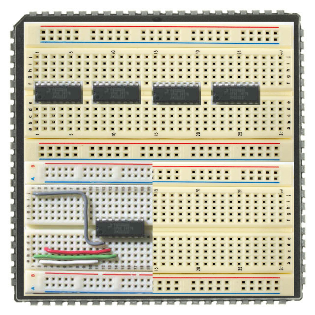
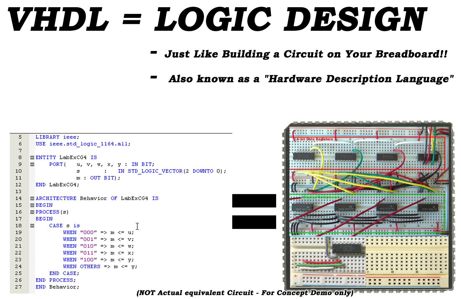
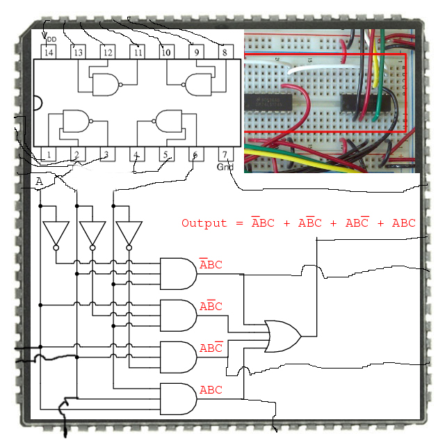
VHDL is described as a Logic "Hardware Description Language". Essentially what this means is that VHDL is a code Equivalent, for the process of placing interconnections (Wires) and digital components (7400 Series IC's) on a Breadboard for designing a completely Digital Circuit within software. I emphasize the term "DIGITAL" as VHDL code will only be able to implement digital circuits. Any "Analog" electronics has to be connected externally to the CPLD. Try to envision the following explanation in terms of a Digital circuit on a breadboard using standard Discrete Logic components like the popular 7400 Series Motorola IC's as shown below.
What you have to realize is this, the VHDL code you write, simply determines the "wiring" of interconnections and the placement of Discrete logic components (7400 Series IC's) that you would have in a digital circuit, like that on a prototyping Breadboard. The code is not actually a program really... like that used in computer software. It is more of a set of procedures that tells the Software how you want your digital circuit to be connected within the CPLD or FPGA. Your Circuit design code (VHDL) is then FLASHED onto the Chip. Once your VHDL Code has been FLASHED onto the CPLD, it has already completed its job...which is just wiring up the Digital circuit. This is all done before the CPLD is even activated or powered on for the first time. VHDL is a mere set of construction commands for building a digital circuit. VHDL is a "HARDWARE DESCRIPTION LANGUAGE". :) Get it ?? So, your entire set of VHDL code is more like a set of Procedures for building a Digital circuit.
Now remember a Digital circuit regardless of all the different discrete component IC's you have incorporated within it..... They will all run independently at the same time; reacting in real time to digital Inputs and output signals. Well guess what!!..... your CPLD with your VHDL circuit design will operate exactly the same way as any Digital circuit on a Breadboard would. All the Discrete components or "GATES" will all operate independently of each other. Another way of looking at it.... is that the "GATES" will all run at the same time. Your VHDL code design, once it has been flashed to the CPLD, and it has been powered on.....It will run and operate just like a digital circuit made out of discrete logic 7400 series components on a breadboard.....all reacting to digital input signals in real time. ALL THE GATES IN THE CIRCUIT ARE RUNNING IN PARALELL!!
So if you think about it, all of your Blocks of VHDL code (referred to as "PROCESSES") are being executed at the same time too. When you FLASH Program a VHDL block of code onto a CPLD..... this is simply the virtual act of "Wiring up" your Digital circuit. All of the VHDL code processes are all executed exactly at the same time….. all in parallel. A CPLD is essentially a chip that replaces the function of simple Digital circuits with several Discrete components. In Essence, using the VHDL code, you dictate how the components inside the chip will connect to each other and which connections from the circuit will connect to the external Pins on the CPLD as well. This is all specified within the VHDL code. Interconnections, Logic Functions, CPLD Pin designations and even sequential functions can be implemented. So with VHDL you can actually have a mix of Parallel processes running and also have embedded sections that run sequentially. However, at the beginning it is extremely important to visualize the VHDL language as a code equivalent, of a person writing down the Wiring procedures for building a digital circuit on a Breadboard. Like the Classic 7400 Series chips shown below: With each line of VHDL code that you write, you are essentially adding Wires and Components to a Breadboard.
So Essentially VHDL is this:
AFTER YOU FLASH THE CHIP WITH YOUR VHDL CODE AND YOU POWER UP THE CPLD….
Not all of the code is executed sequentially one line of code after the other like a software based computer program does. Several Blocks of code (PROCESS's) are all running in Parallel. Because your VHDL code is not a PROGRAM! It's a "Hardware description Language". When you activate your CPLD, it will just turn on and all the Logic Functions that your VHDL code has declared, runs all at once in Parallel, exactly the same way any Discrete Digital component based circuit would function. Just like the classic Motorola 7400 Series components. So just try to always remember this when you are programming in VHDL. When you are done programming your code and Flash that code to the CPLD..... when you turn on the chip to run your design …..it will essentially operate like a 7400 Series based digital circuit.
ALWAYS REMEMBER....... VHDL IS VERY DIFFERENT THAN "C" or "C++" !!!!!
This is probably the number #1 killer for many programmers. They will tend to program all of their VHDL code from start to finish....in exactly the same manner as they would when programming with a "sequential" based programming Language like C or C++. They don't realize that each "PROCESS" Block of code gets executed at the same time running in Parallel. So Remember............ DO NOT PROGRAM IN THIS MANNER!! Get your head out of your ASS and realize you're not understanding how the VHDL code gets executed. EACH "PROCESS" BLOCK OF VHDL CODE GETS EXECUTED AT THE SAME TIME! Again.....VHDL is a Hardware Description Language!
The following Book is a "MUST HAVE". This Text is called “HDL Chip Design” by Douglas J. Smith (1996).
So I would read this book front to back if you want to learn and program in VHDL or Verilog. DOWNLOAD LINK BELOW: ------------------------------------------------------
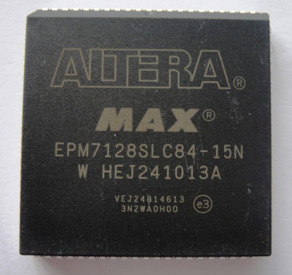
Once you Learn some of the VHDL Basics, and feel you want to try and program an Altera chip, you can use the Altera Quartus II software from the Altera Website. I myself use a Program called “HDL Designer” by the company Mentor Graphics to program my VHDL code. I Then use their other software programs to program my Altera CPLD chip directly through the JTAG port.
For the Mentor Graphics software, I have made several Instructional videos showing how to use their software.
Mentor Graphics HDL Designer Software Tutorials
HDL Designer - "Getting Started" (HD - Video)
For some Extra Info regarding differences between VHDL Blocks and COMPONENT Blocks visit the Link Below: http://www.digital-circuitry.com/Projects_VHDL_HDL-DESIGNER_01.htm
Mentor Graphics HDL Designer Software Tutorials HDL Designer - "State Diagrams " (HD - Video)
Mentor Graphics HDL Designer Software Tutorials HDL Designer - "Running a ModelSim Waveform simulation" (HD - Video)
Mentor Graphics HDL Designer Software Tutorials HDL Designer - User Declarations Settings - Assigning PORT Names to FPGA Pins (HD)
Mentor Graphics HDL Designer Software Tutorials HDL Designer - Compiling your FPGA SOF / POF files with Precision Synthesis (HD)
Mentor Graphics HDL Designer Software Tutorials HDL Designer - Adding Custom Buttons to ModelSim WAVE window. (HD)
VGA Interfacing | VHDL Programming | PONG VIDEO GAME See my Devoted Webpage for this Project.
Need some help with your VHDL programming ? Join the edaboard.com Forum. http://www.edaboard.com/forum30.html Connect with other professionals, to discuss and troubleshoot your VHDL code or anything related to Engineering. A Great learning resource with lots of links and references. Join Today!
|
|
|
||