|
Current Time:
|
|
|
|
|
Gerry's Electronics & Robotics Laboratory -=SOLDERING=- -=MY BENCH=- -=MY ROBOTS=- -=PCB FAB=- -=CHIPPERY=- |
|
-= WELCOME TO GERRY'S ROBOTICS PAGE =- -=ER-III=- -=ER-4PC=- -=CRS PLUS=- -=CRS A250=- -=PNEUMATICS=-
|
||
-=CRS ROBOTIC ARM YAHOO GROUP =- Please Join my CRS ROBOTIC ARM Yahoo Group! Let's all connect and share our Resources to get our CRS Robots up and running. http://groups.yahoo.com/group/CRS_ROBOTIC-ARM_GROUP
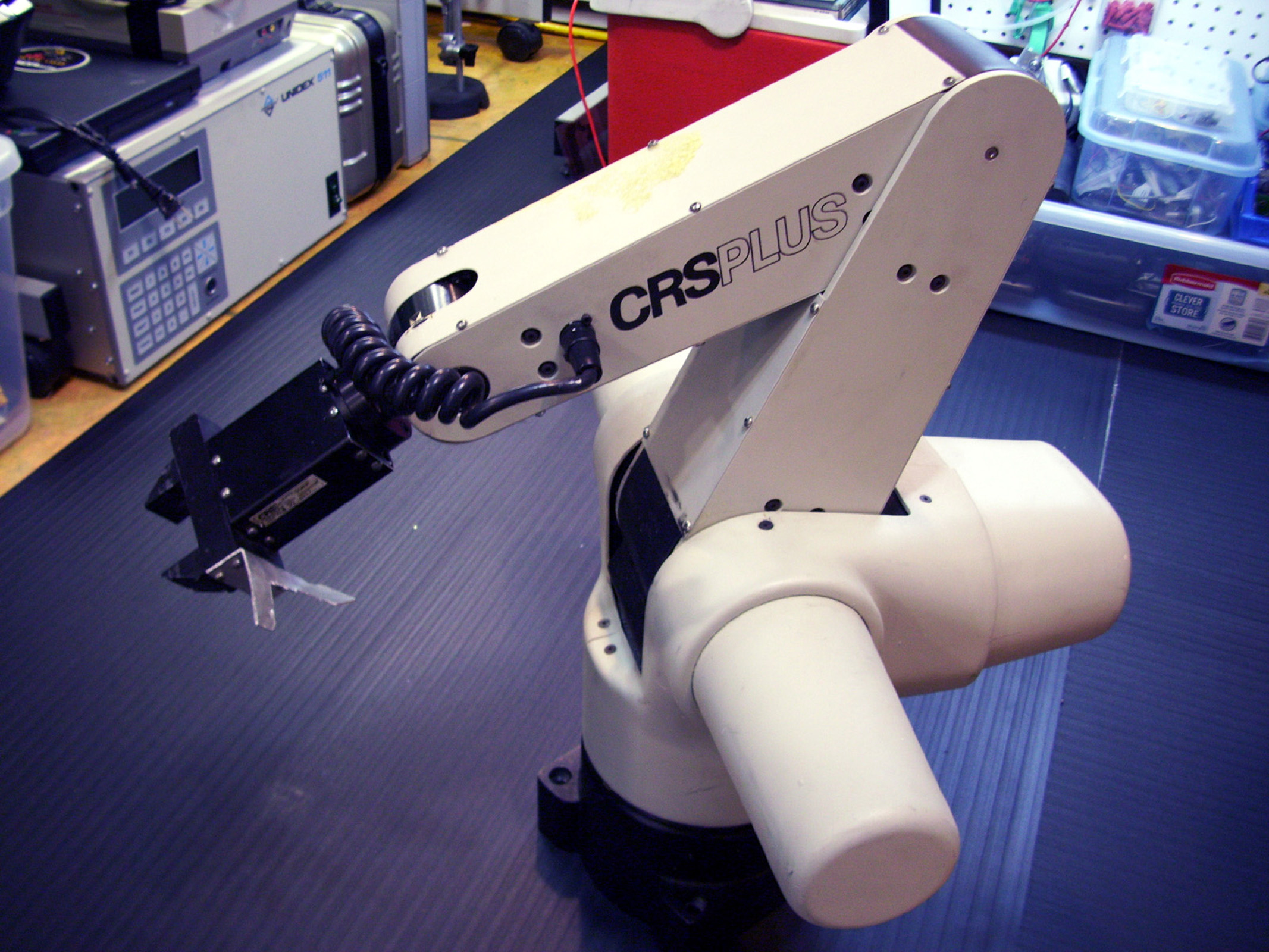
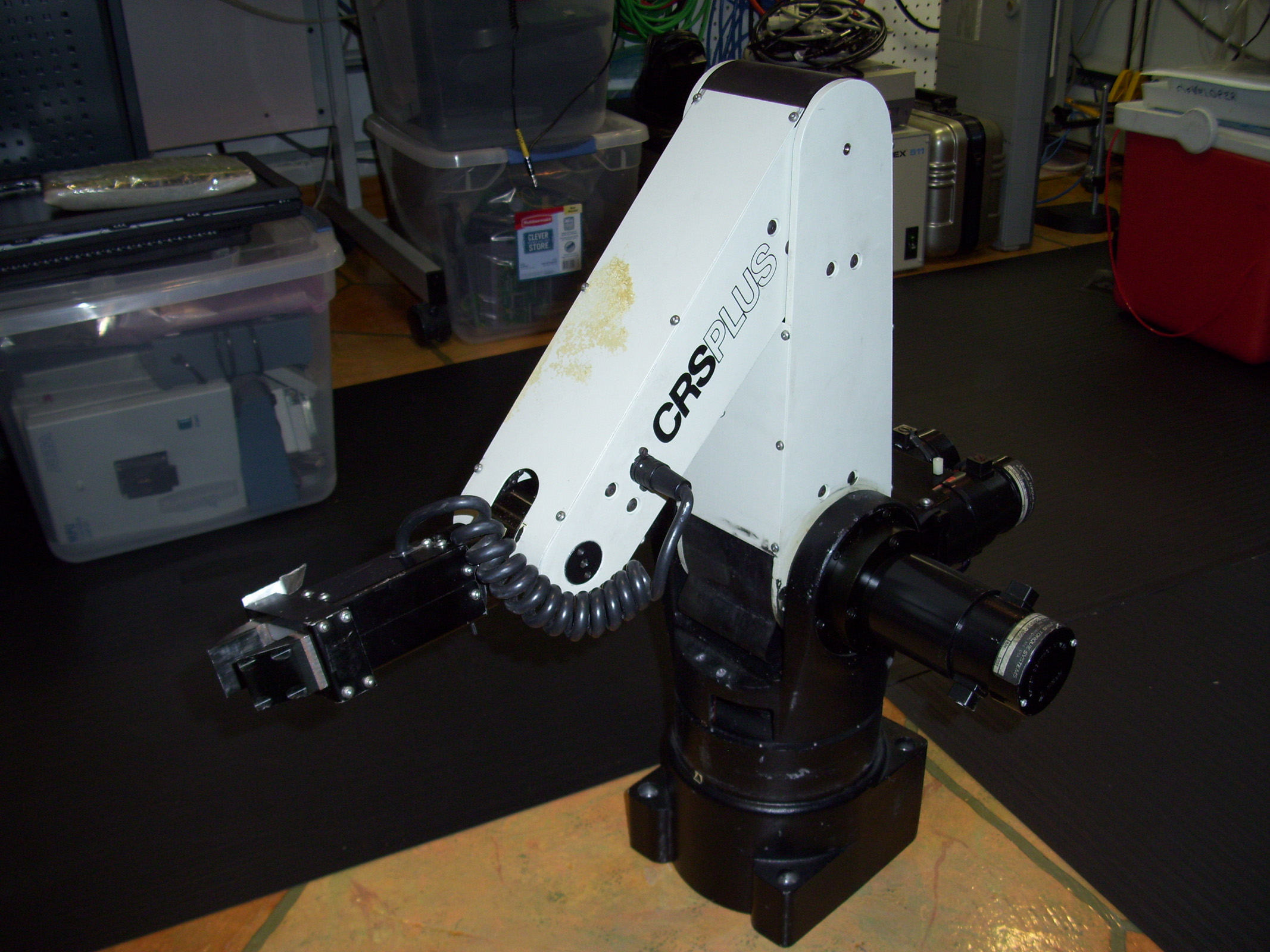
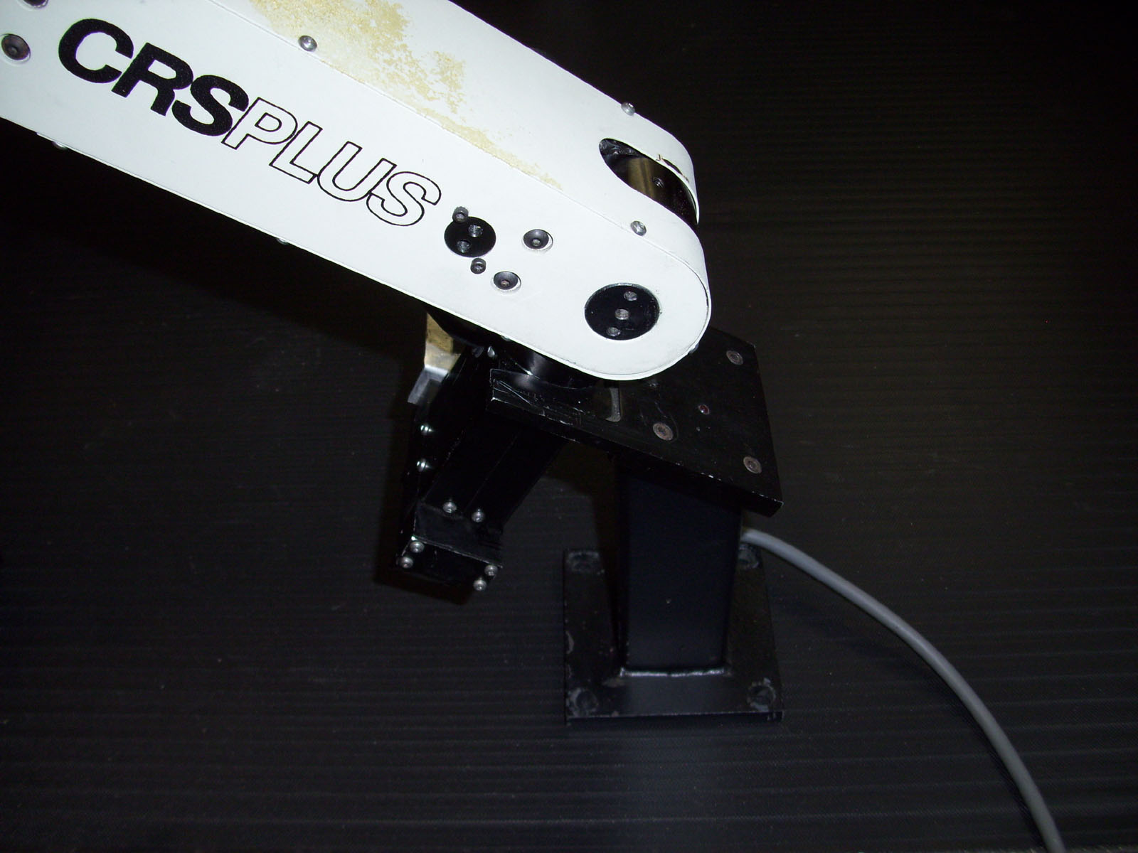
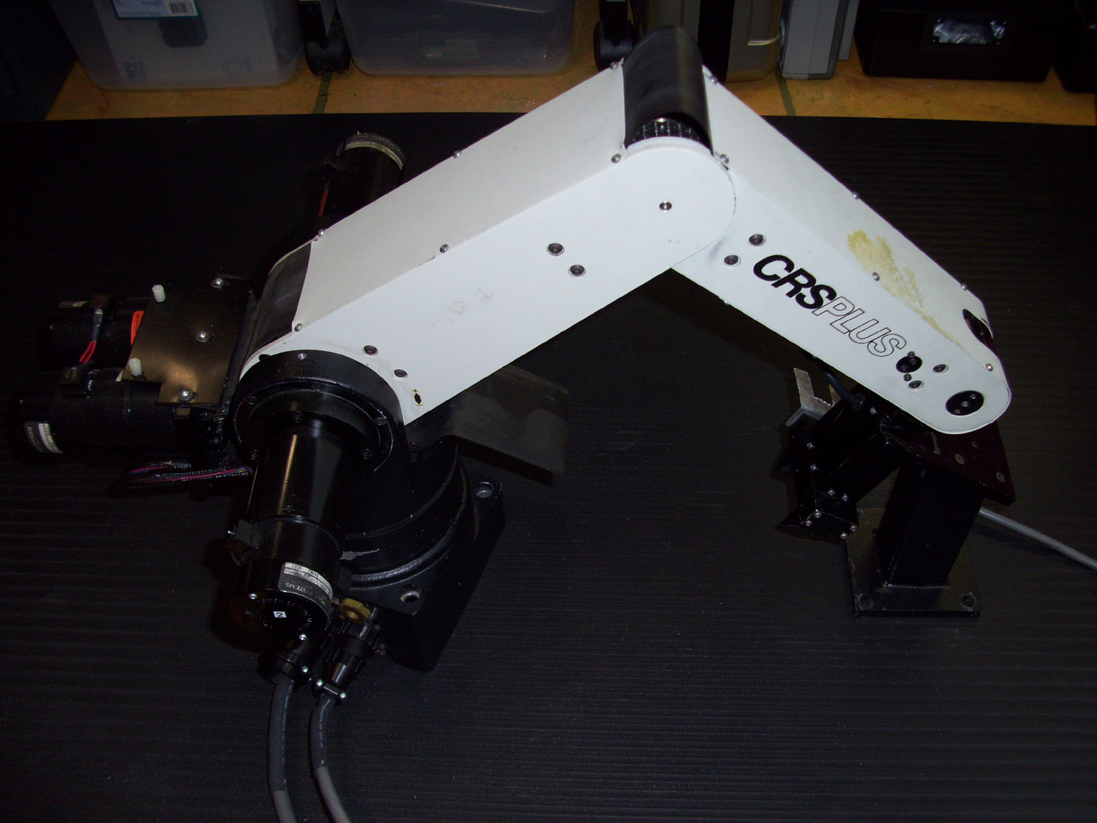
My New CRS+Plus Robot Arm Model "A250"
The plan is to perform a "MOD" on this robot so that it will operate with an SRS-M1A controller that is normally used with the "SRS-M1A" model Robot Arm. Essentially what I am doing is re-wiring the Robot Umbilical cable that connects between the Robot & the controller, so that I can use the SRS-M1A controller with an A250 model Robot. :)
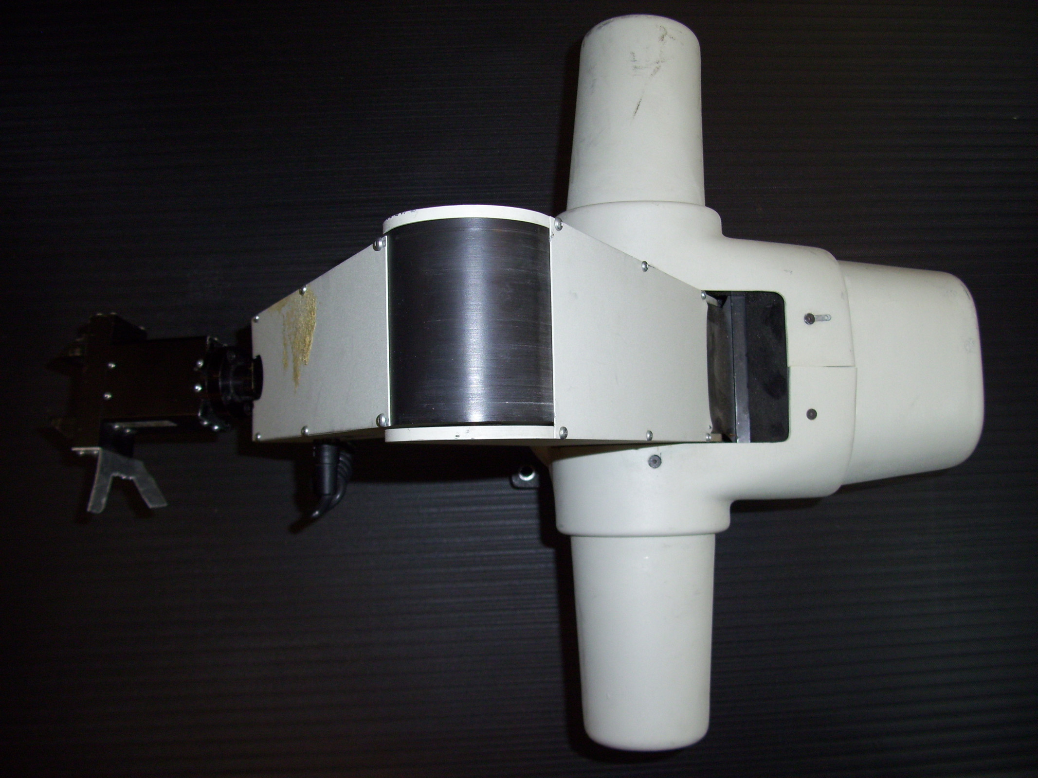
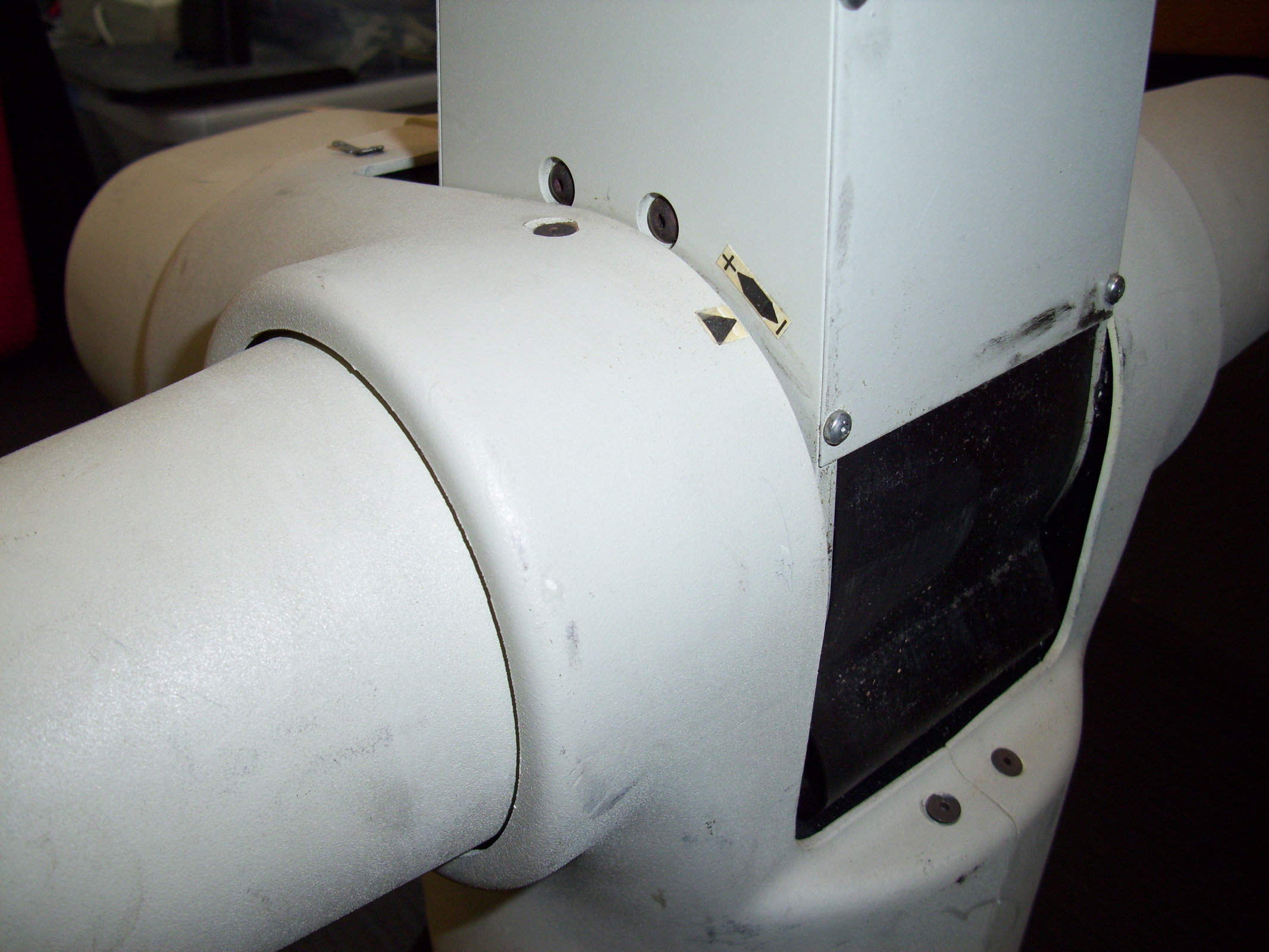
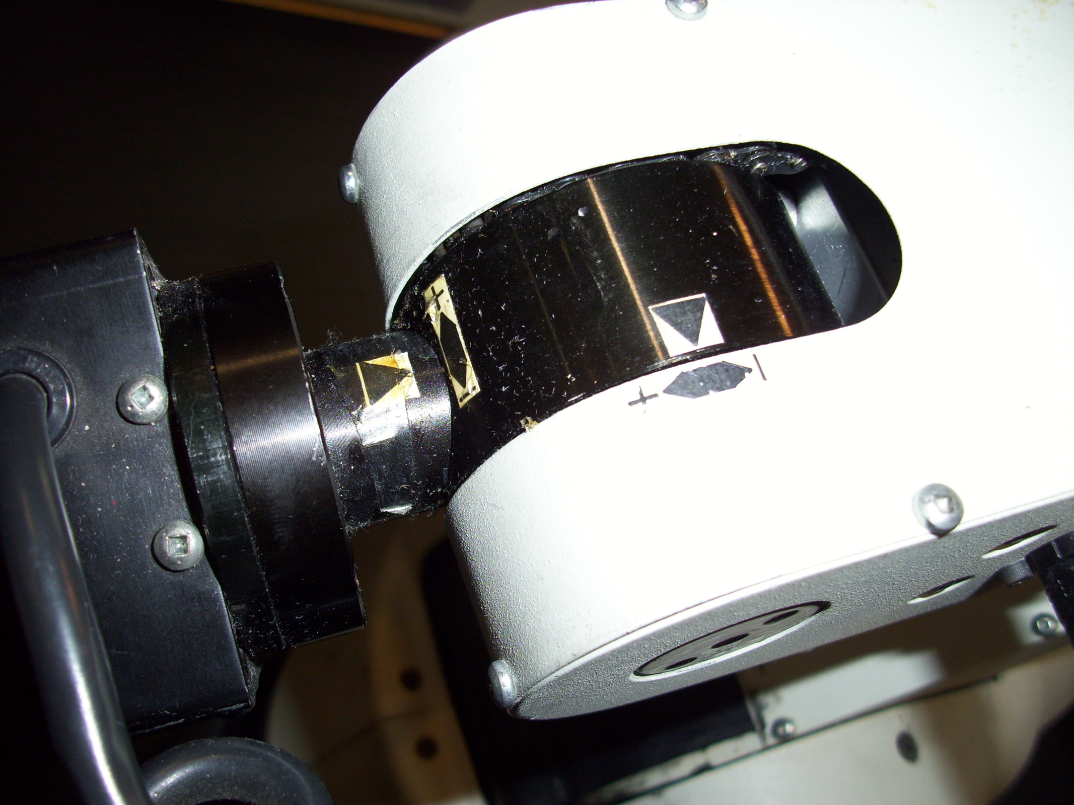
As you can see in the Images above, each joint on the robot has a "Homing Marker". These need to be aligned prior to running the Homing sequence within the ROBCOMM II Software.
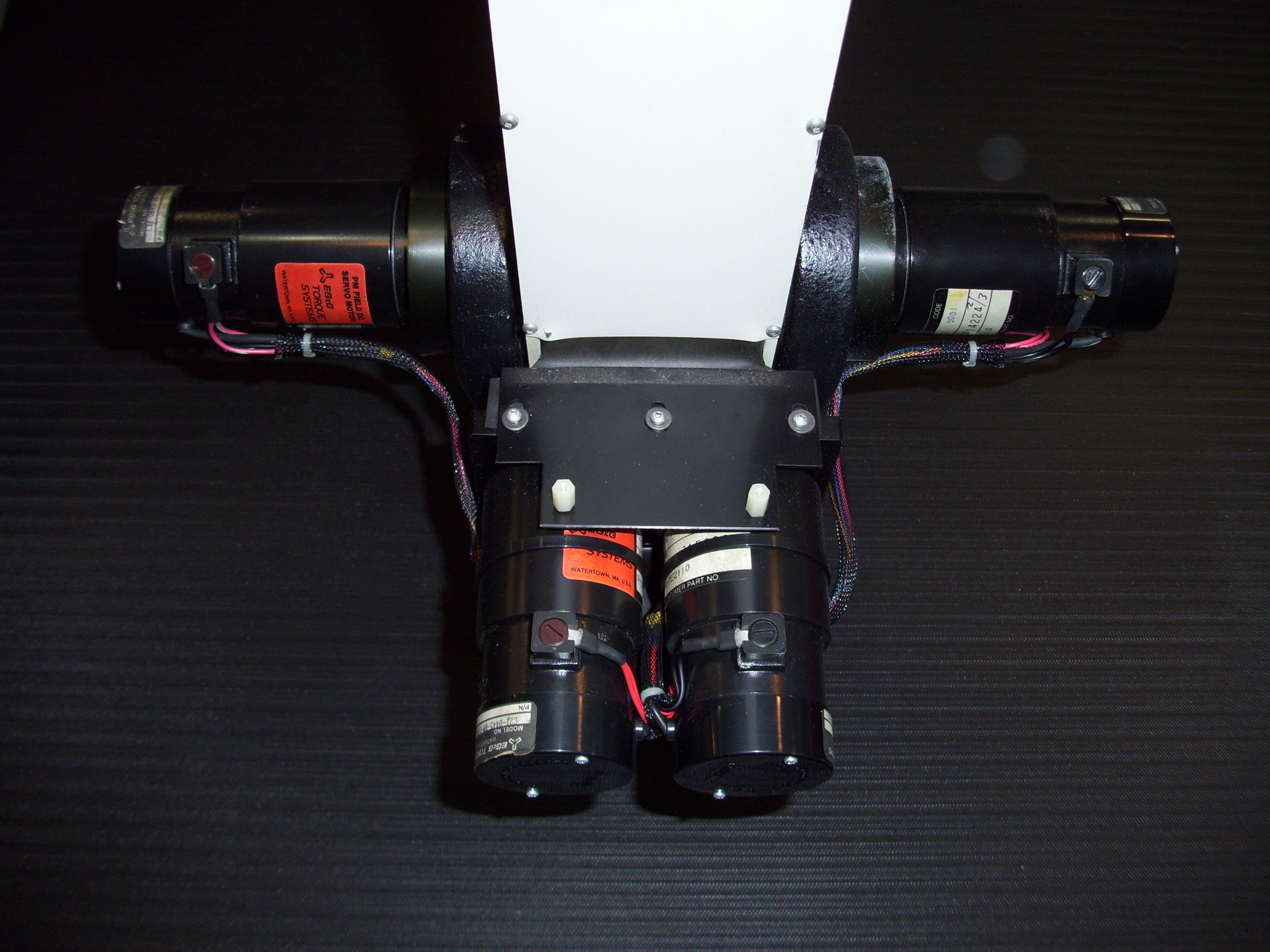
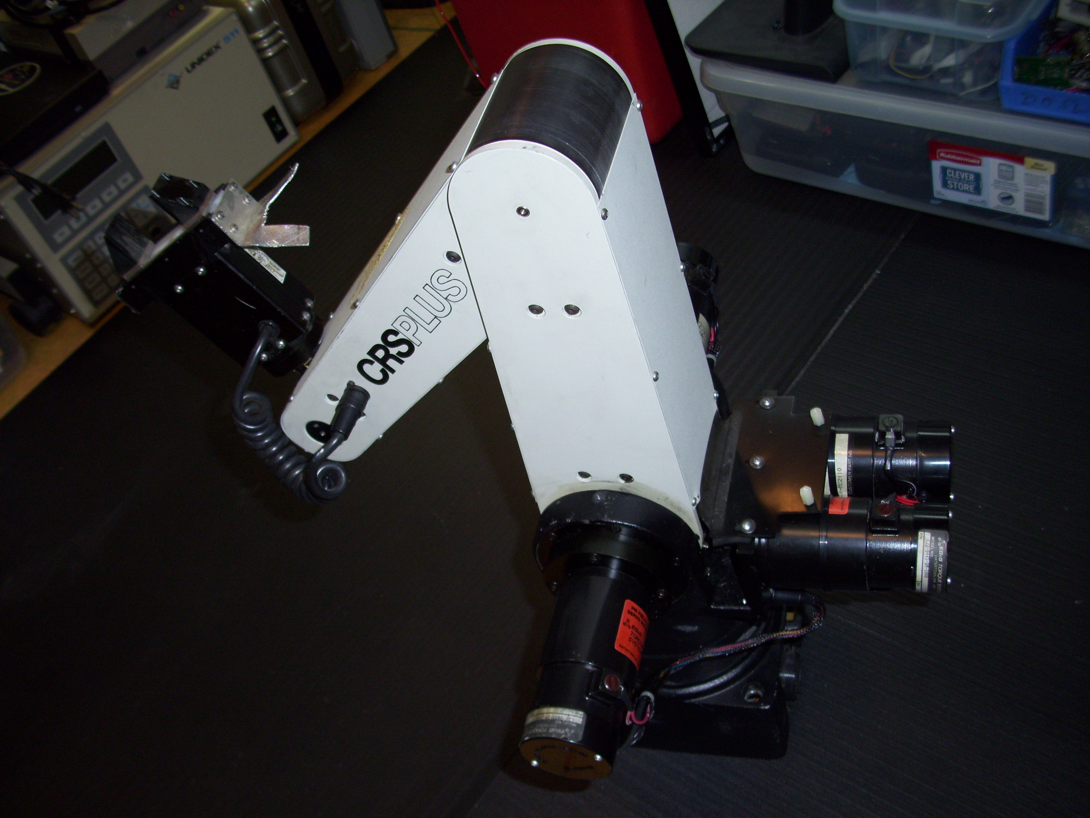
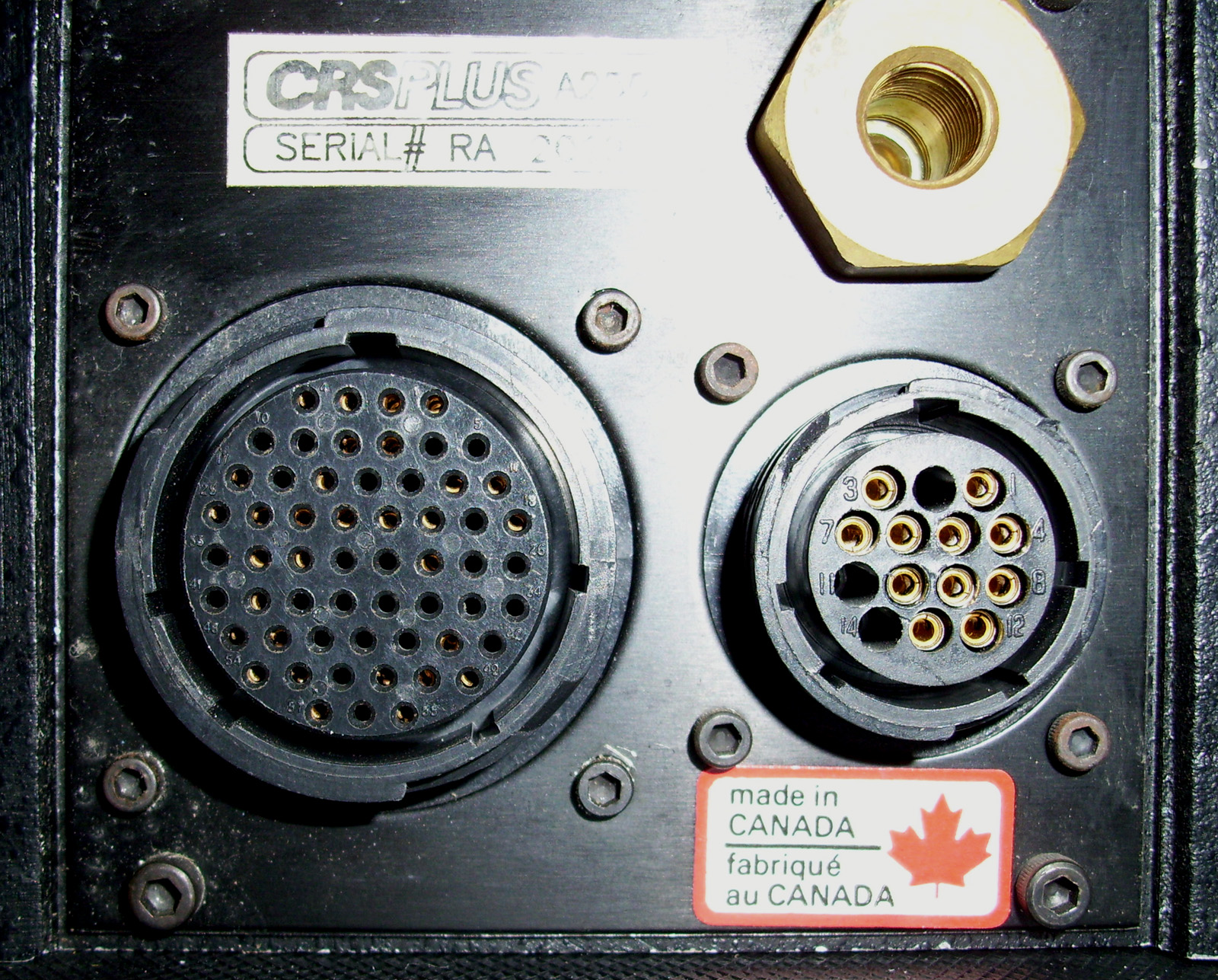
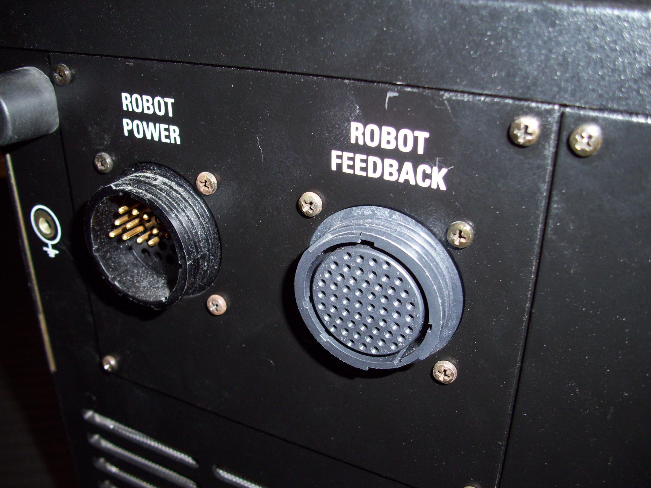
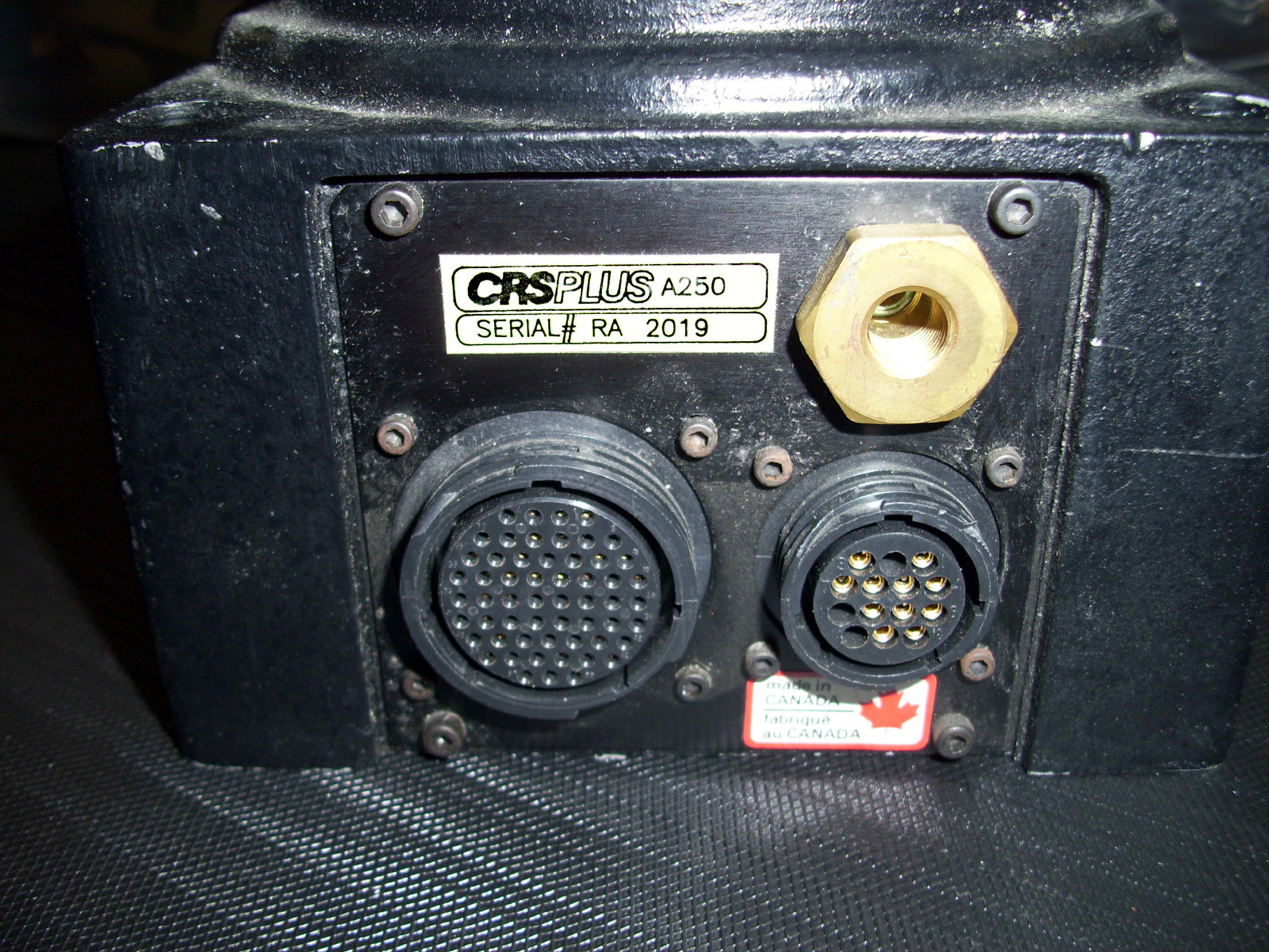
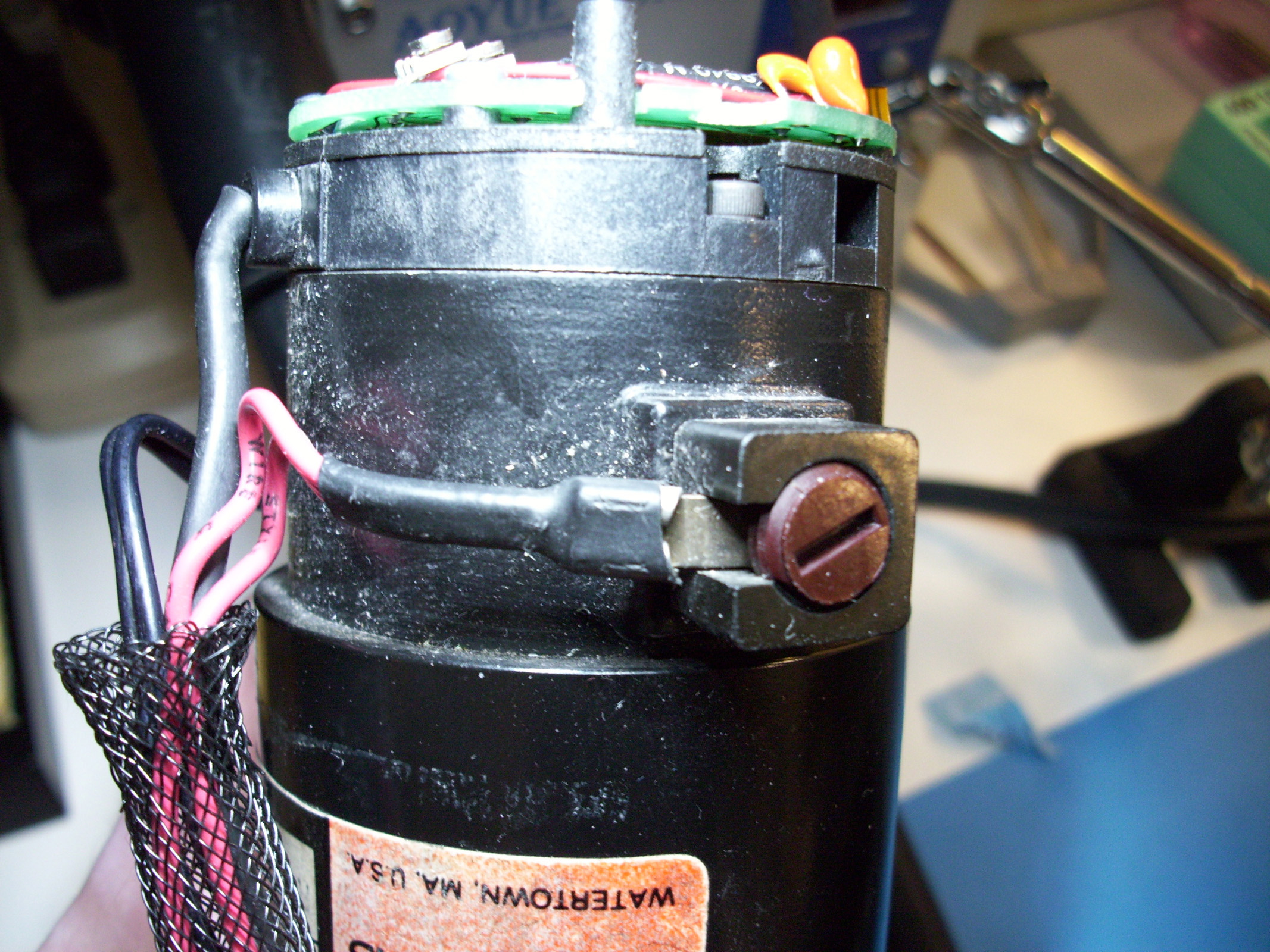
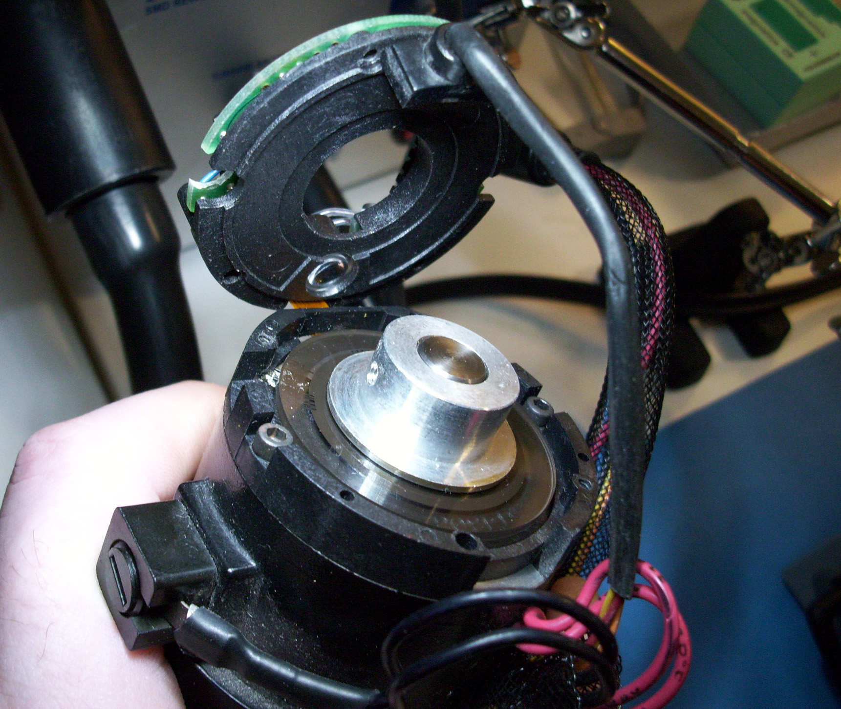
After removing the External housing, the A250 robot looks similar to the older M1A versions. With the Motors and their Encoders exposed, this reveals that the only real difference (in regards to electronics)....between the M1A and the A250 robots; is their Interface ports. The A250 as shown here uses "CPC" connectors, and the M1A uses "EDAC Series 516" connectors.
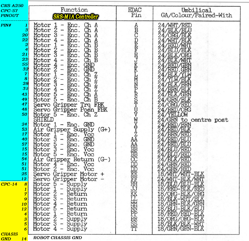
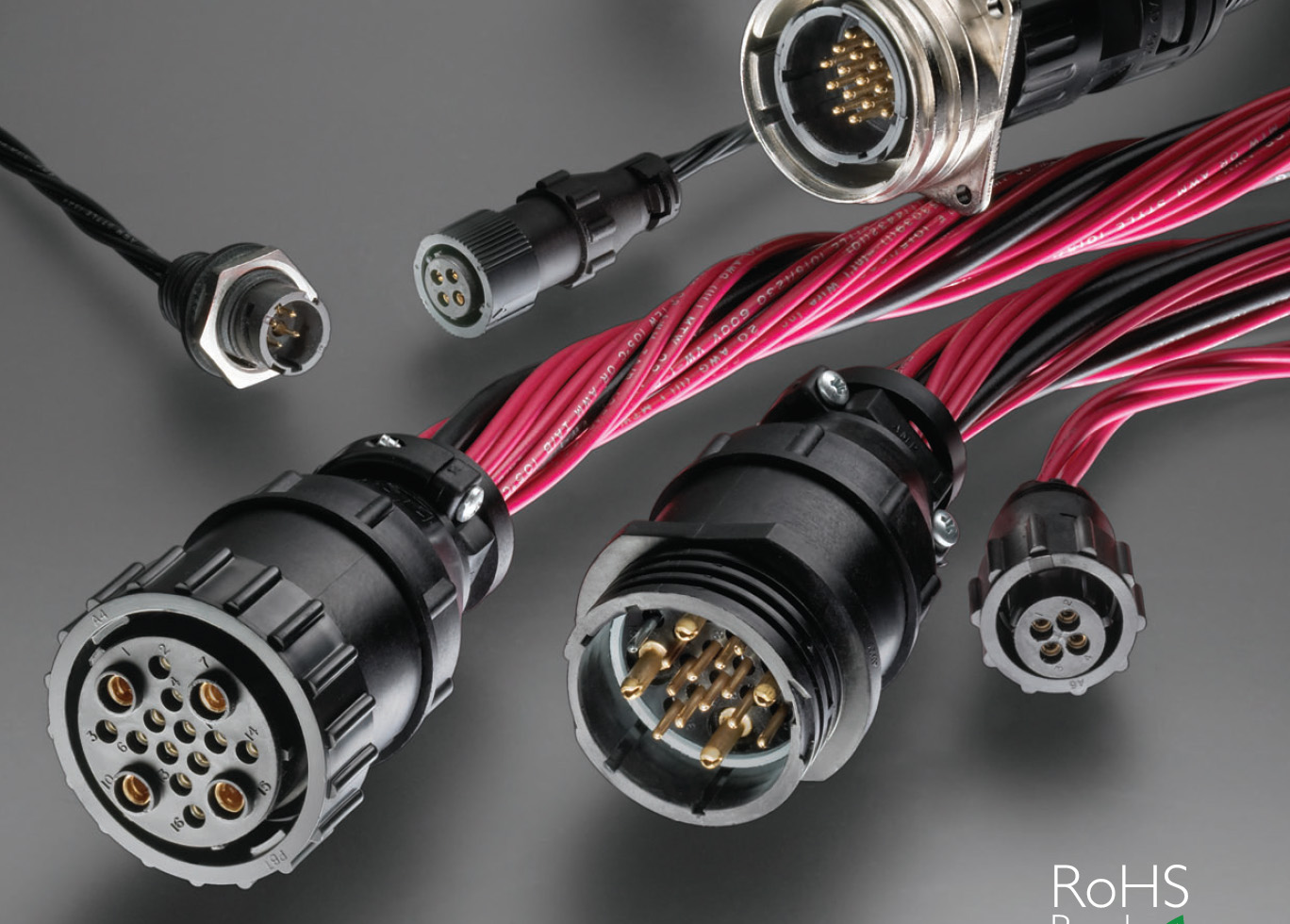
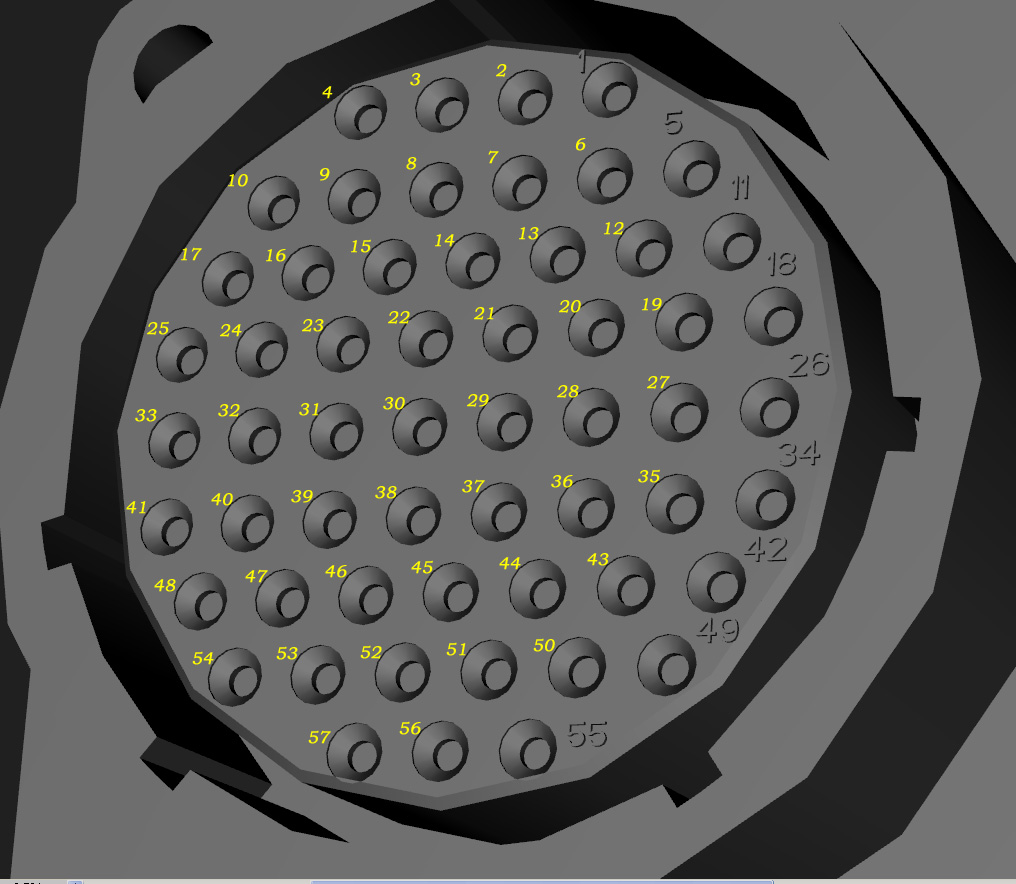
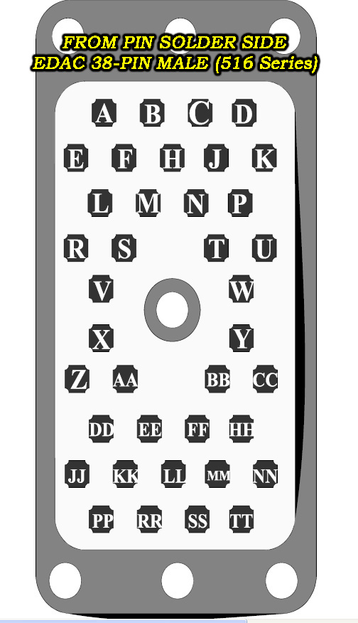
Below are the Pinout connections for the CRS PLUS A250 Robots "CPC-57" Feedback connector, and the "CPC-24" Robot Power connector; in relation to the SRS-M1A Controllers "EDAC" Robot Arm interface port.
The SRS-M1A Controllers "EDAC" connector entails both the Robot Encoder Feedback connections and the Robot Arm's Motor power connections. Shown below are the CPC connectors that are normally used with the A150, A250 & A255 model CRSPLUS Robots and their corresponding controllers like the C500c Controller that is used with the A255 robot.
CPC CONNECTOR ORDERING DATASHEET: http://www.digital-circuitry.com/FILES/CRS_Robot/CPC_Connectors/CPC_sections_1-57.pdf
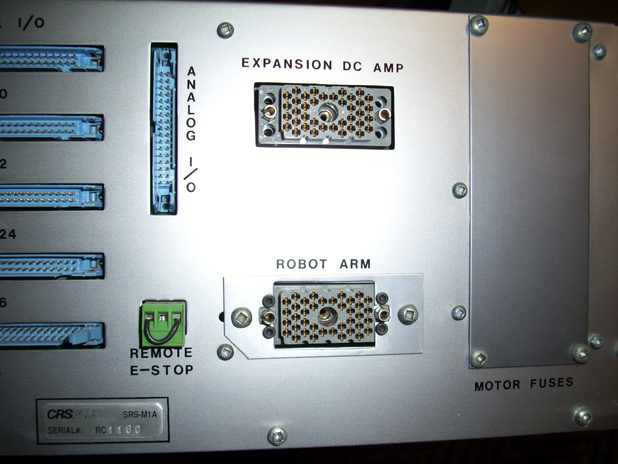
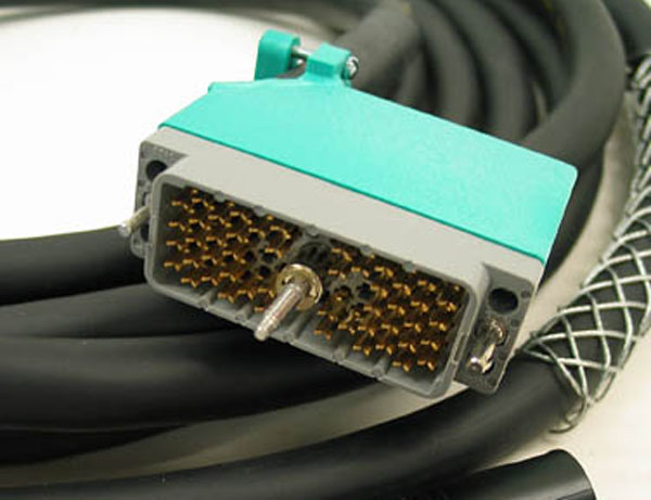
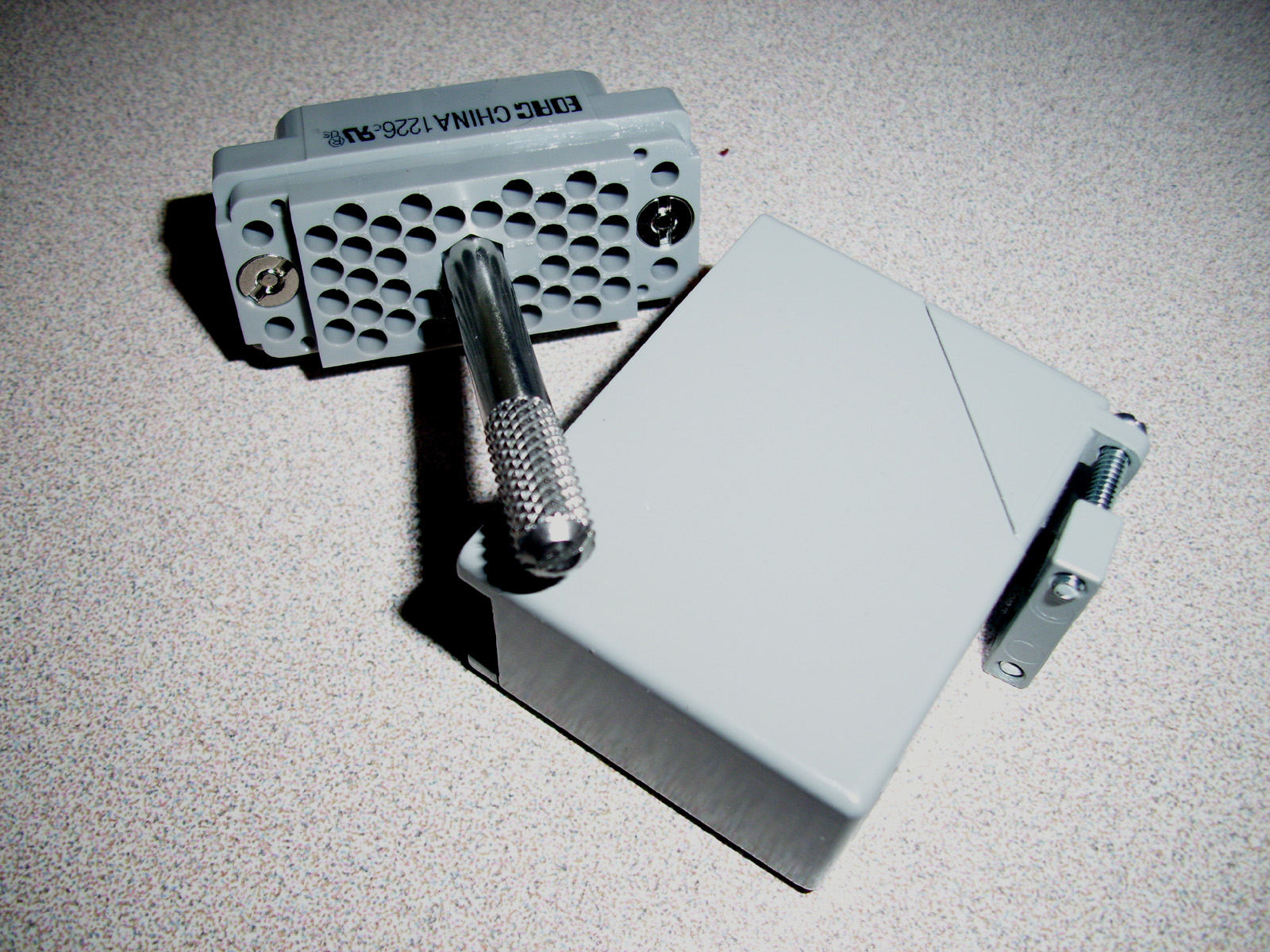
EDAC Series 516 Connectors used with the CRSPlus M1 Robot and the SRS-M1A controller as shown below:
EDAC SERIES 516 ORDERING DATASHEET: http://www.digital-circuitry.com/FILES/CRS_Robot/EDAC_SERIES_516_Connectors/EDAC_Series_516.pdf
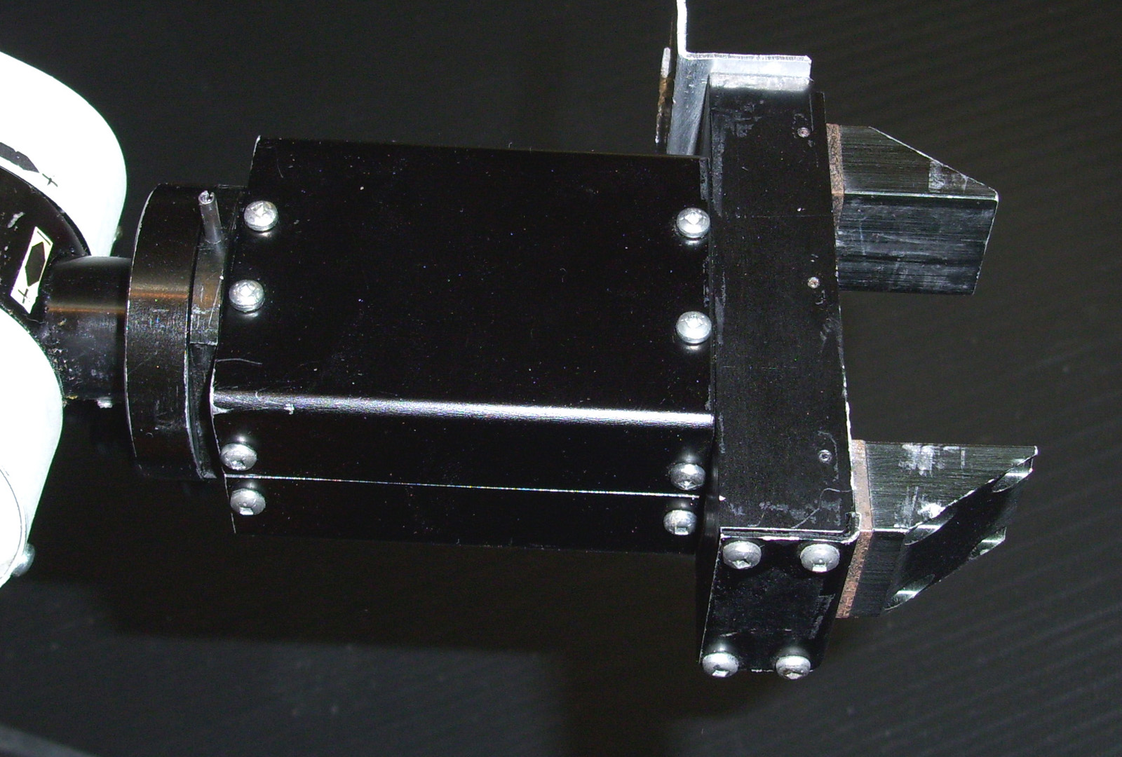
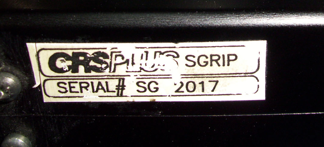
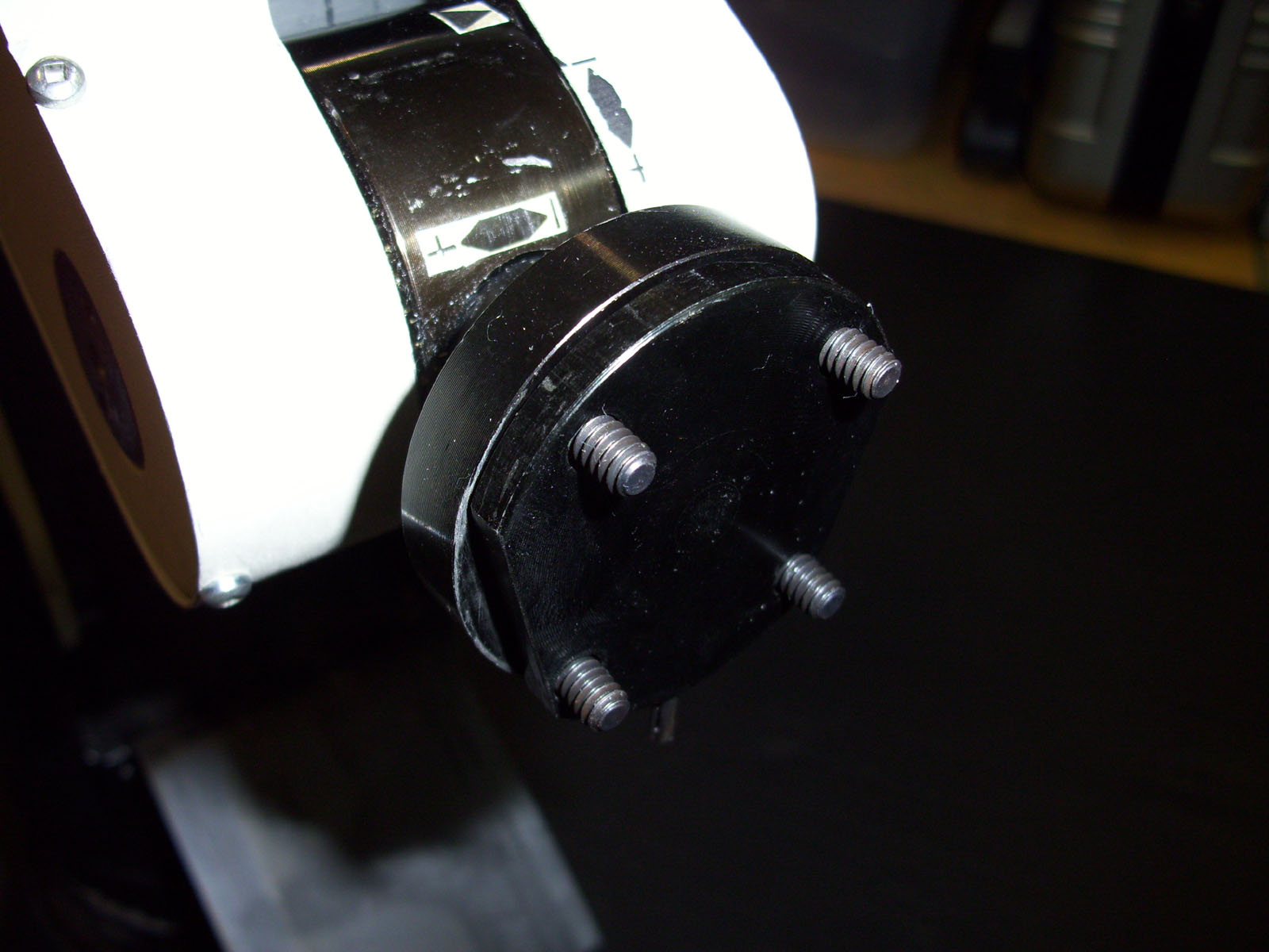
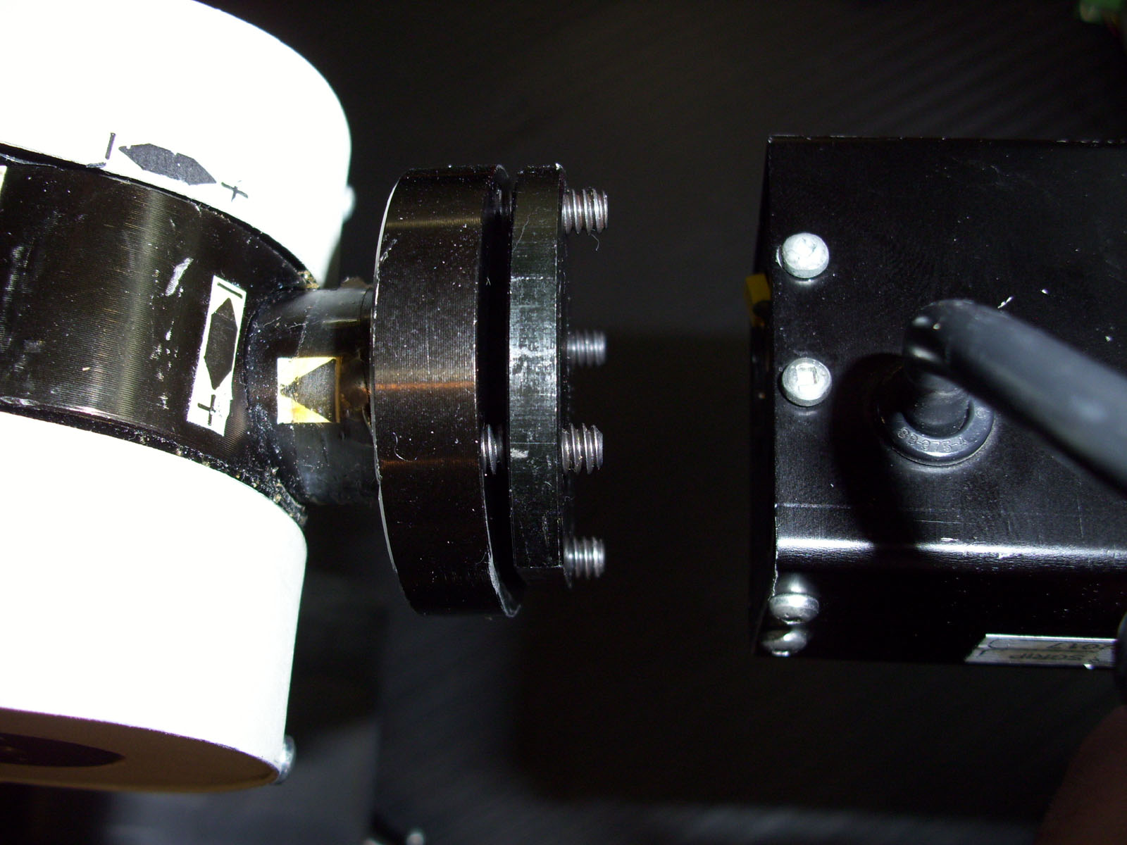
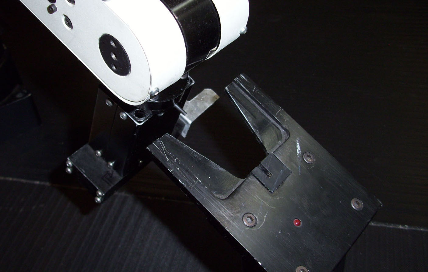
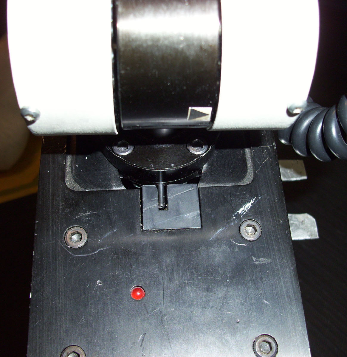
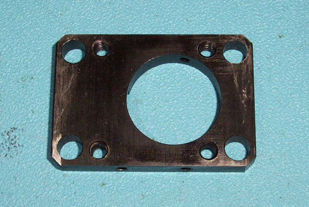
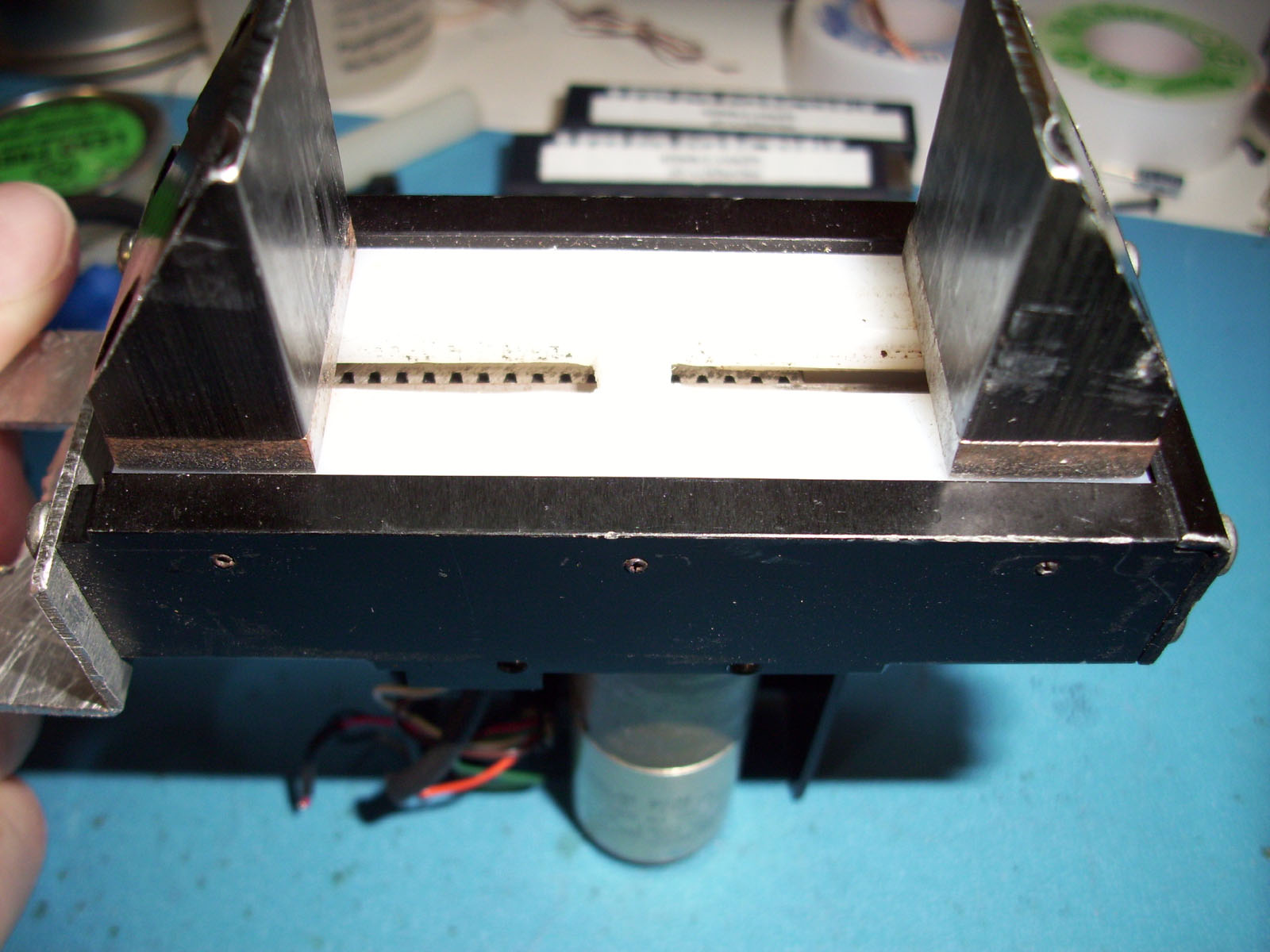
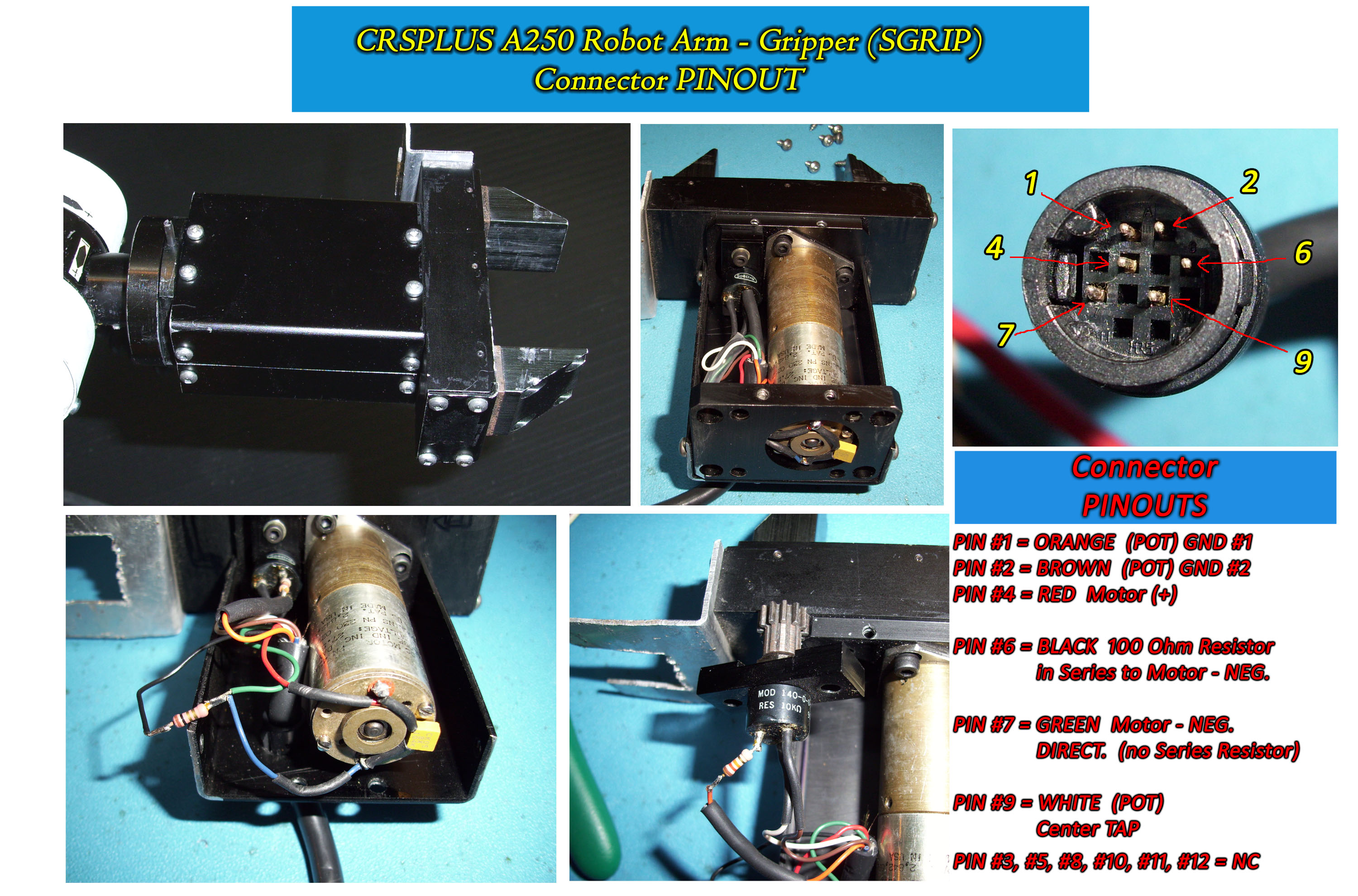
CRSPLUS A250 Robot Gripper "SGRIP"
The CRSPlus Robot has an Accessory called the "HOMING POST" or "HOMING MAST". As seen in the Photos above, there is a Steel plate that is added in between the Gripper and the Wrist assembly. You will notice a small protruding PIN attached. The PIN is used to activate a proximity sensor that is mounted to the top of the Homing Post. When the Robot arm docks to the Homing Post the Proximity sensor is activated and this signal is used to Calibrate a "HOME" position for the Robot. This is the Primary function for the HOMING POST... to facilitate a Homing Position within the ROBCOMM Software. Each Motor Encoder has a matching Pulse Counter which is part of the Robots Controller Electronics. When the Home position is activated by the Proximity Sensor, all of the Encoder Counters are reset to "00000000" thus indicating a HOME position.
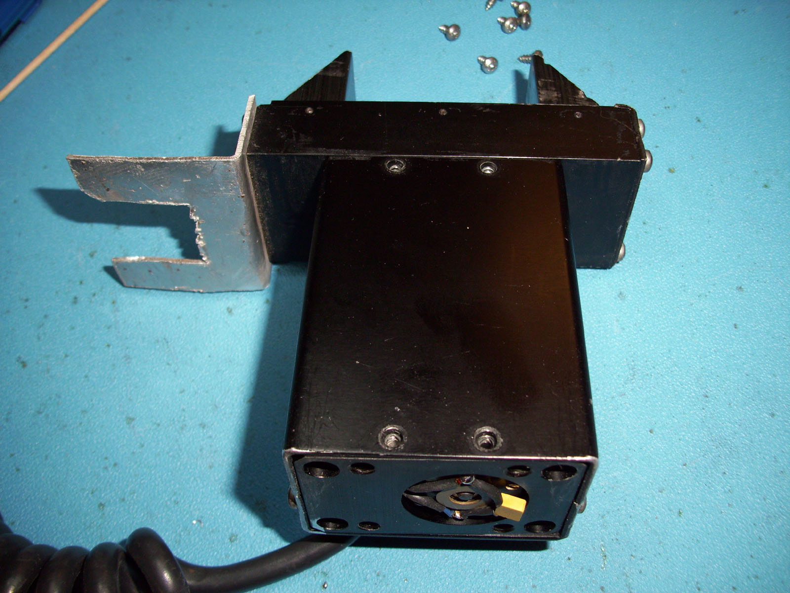
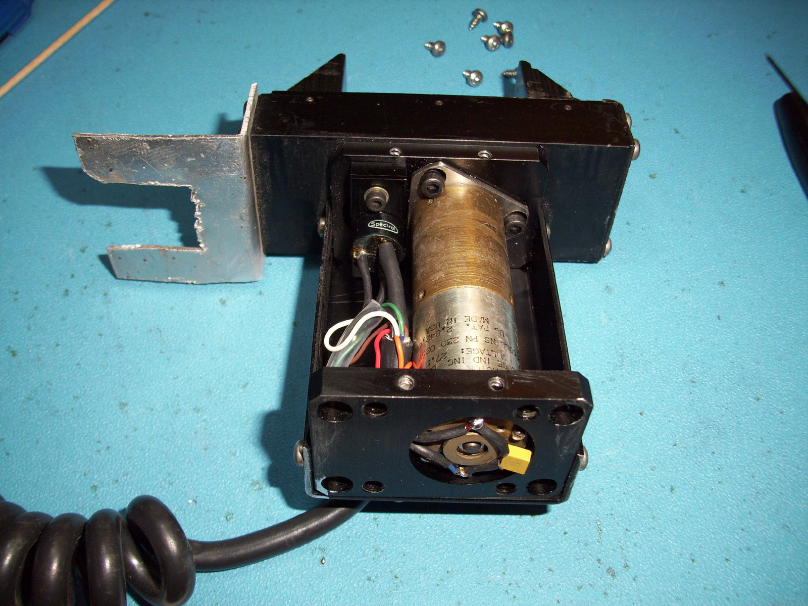
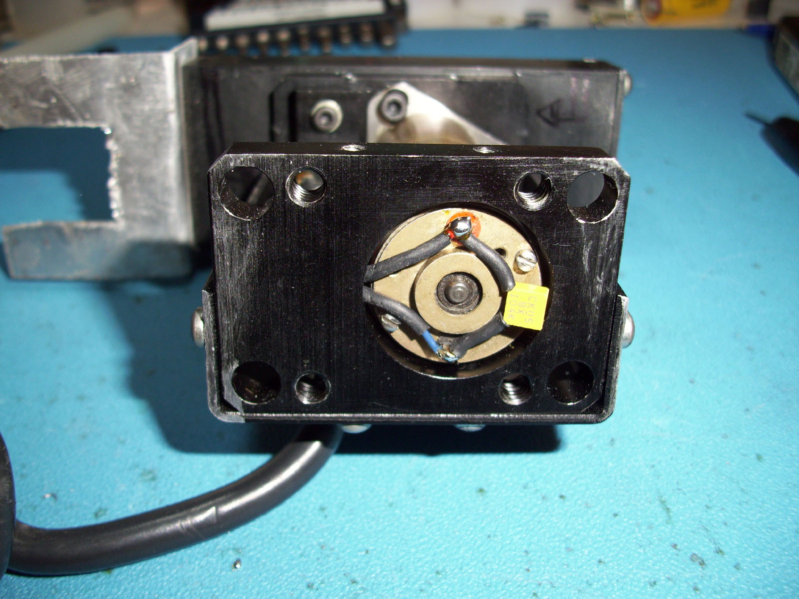
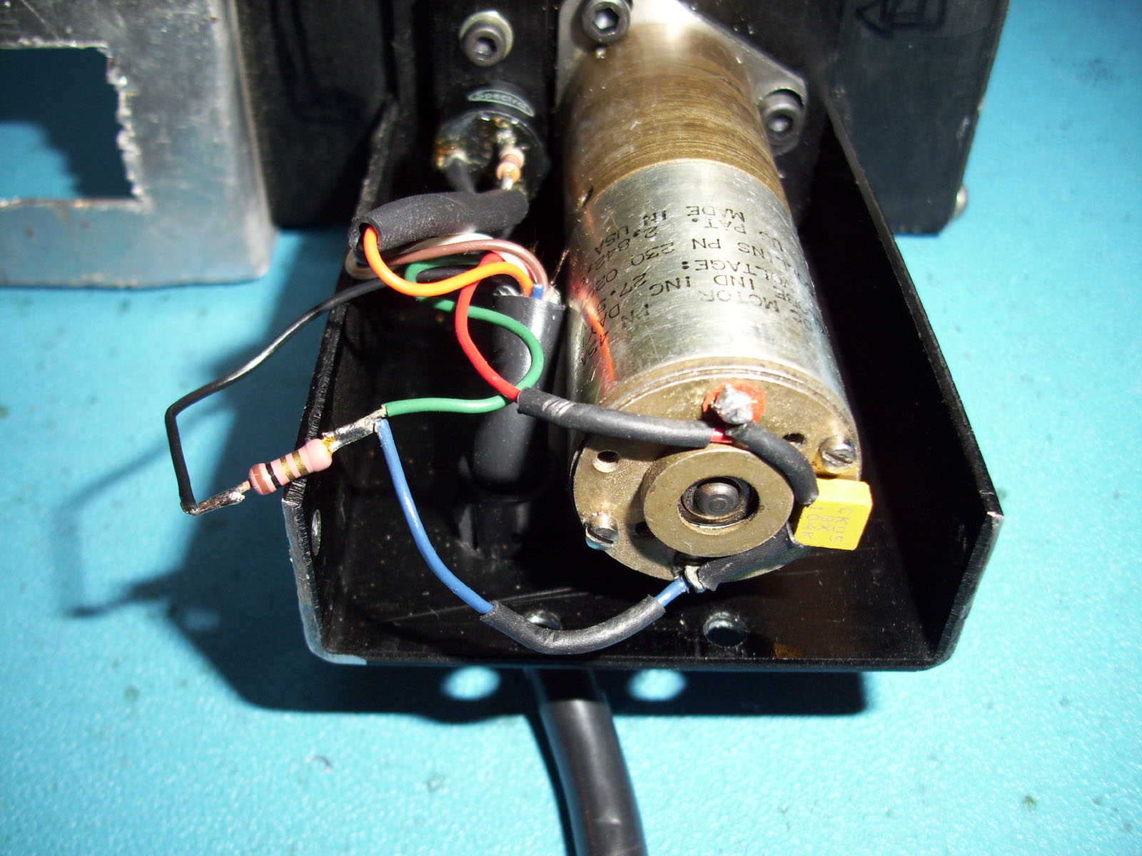
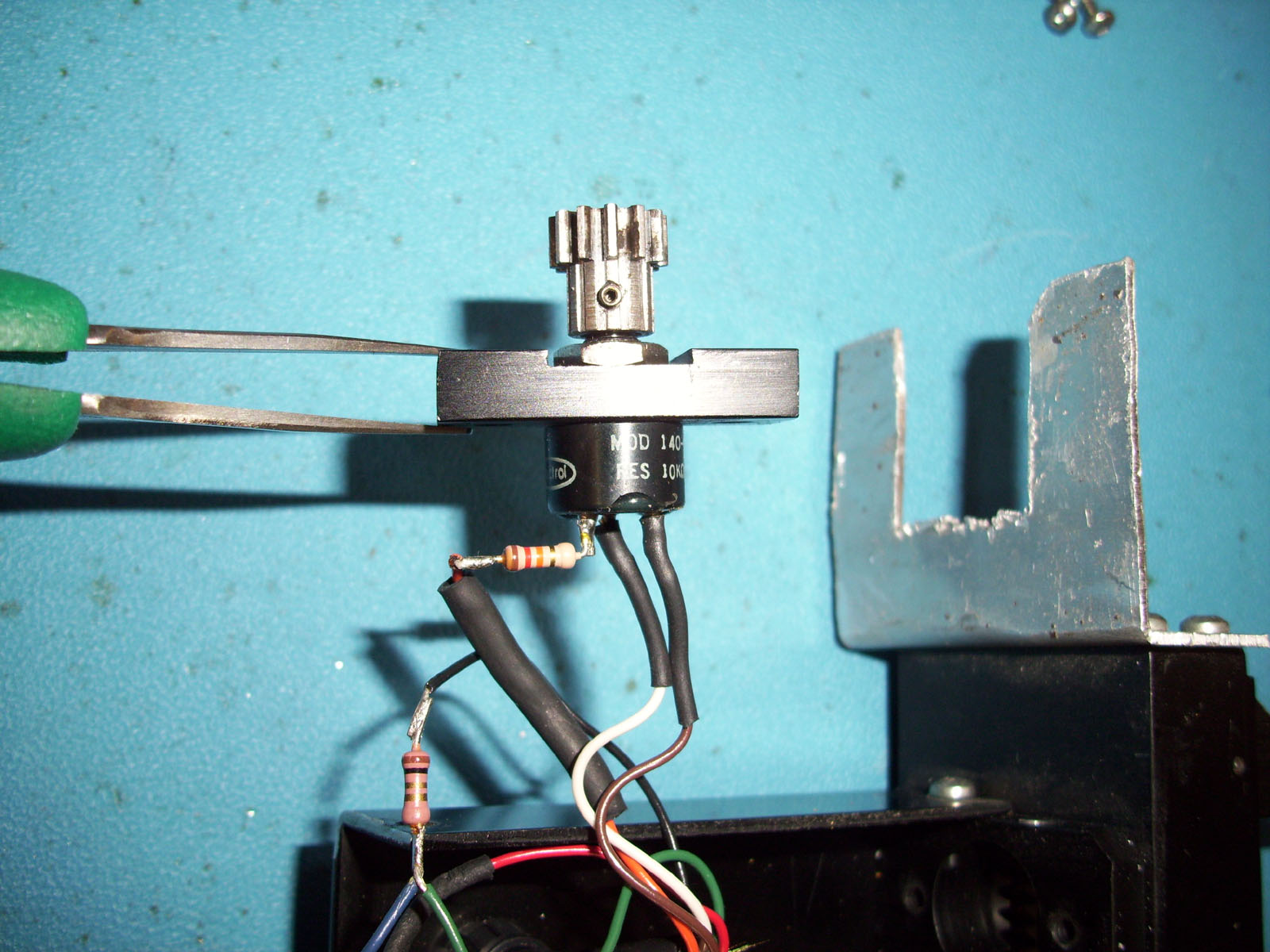
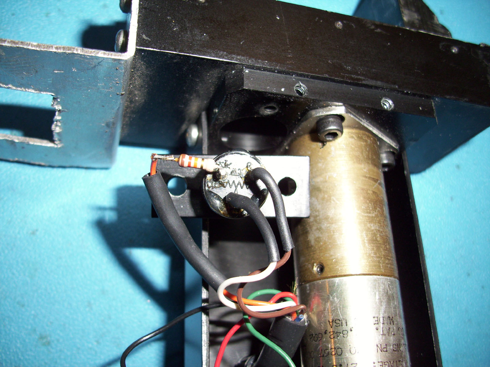
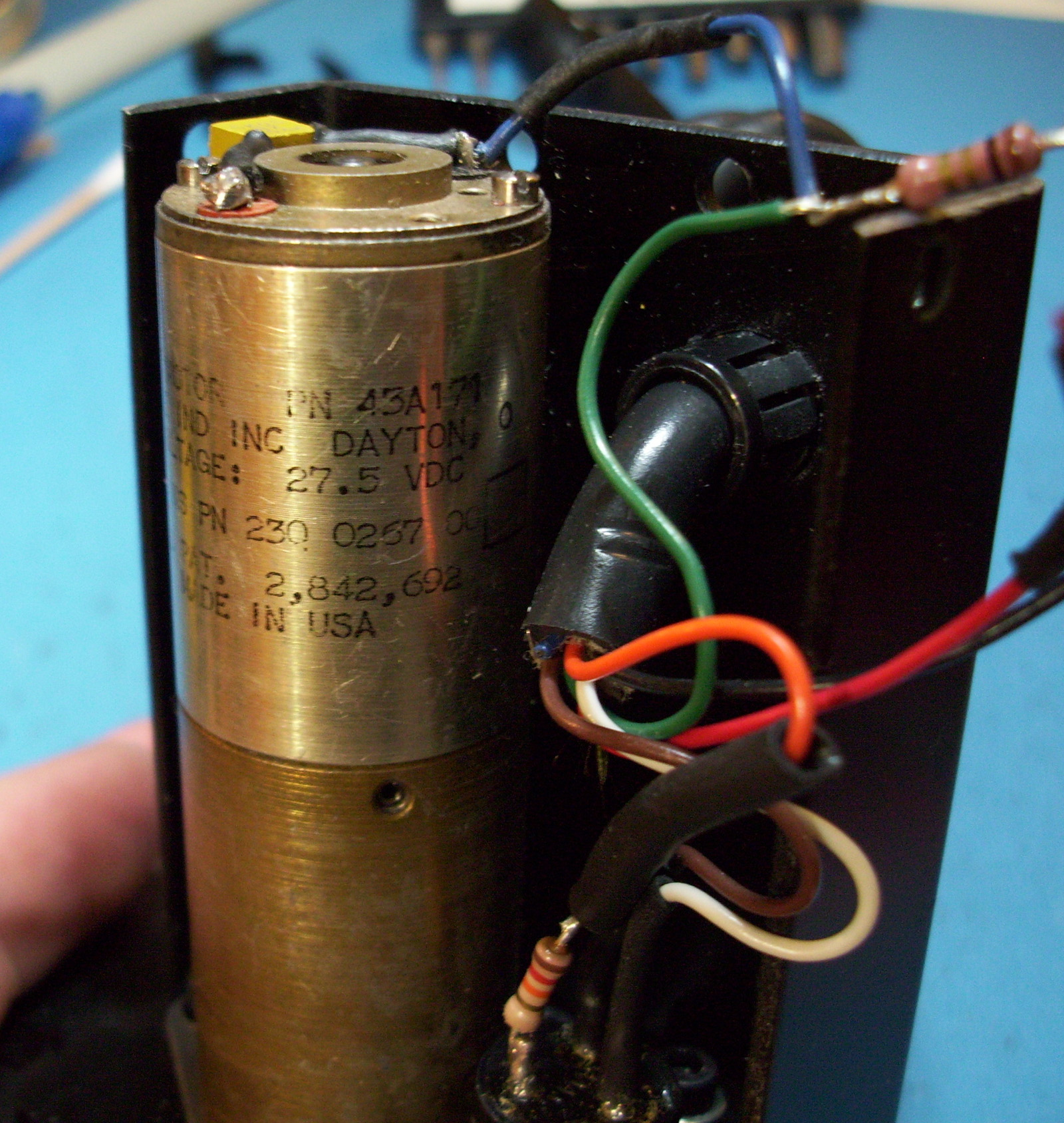
INSIDE THE GRIPPER ASSEMBLY
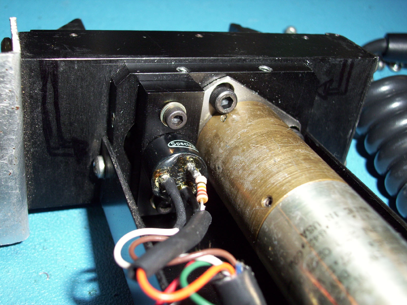
The CRSPlus A250 Gripper Above, uses a 10Kohm position Feedback Potentiometer. There is also a 1 Ohm Resistor connected in Series between Pins Pin #6 coming From the Connector, which then connects to the Motors (-) NEGATIVE Terminal. However, Pin #7 connects Directly to the Motors NEGATIVE Terminal, bypassing the 1 Ohm resistor completely. This Pin #7 could be used for "Motor-Voltage-Feedback" by the controller. Notice that the Motor is rated for a Maximum Voltage of 27.5 Volts DC. The POTENTIOMETER has its "CENTER TAP" connected to PIN #9 (WHITE WIRE). The POT's COIL ends (GND #1 & GND #2) are connected to PINs #1 & #2 accordingly, however PIN #1 (ORANGE WIRE) has a 12Kohm resistor connected in Series.
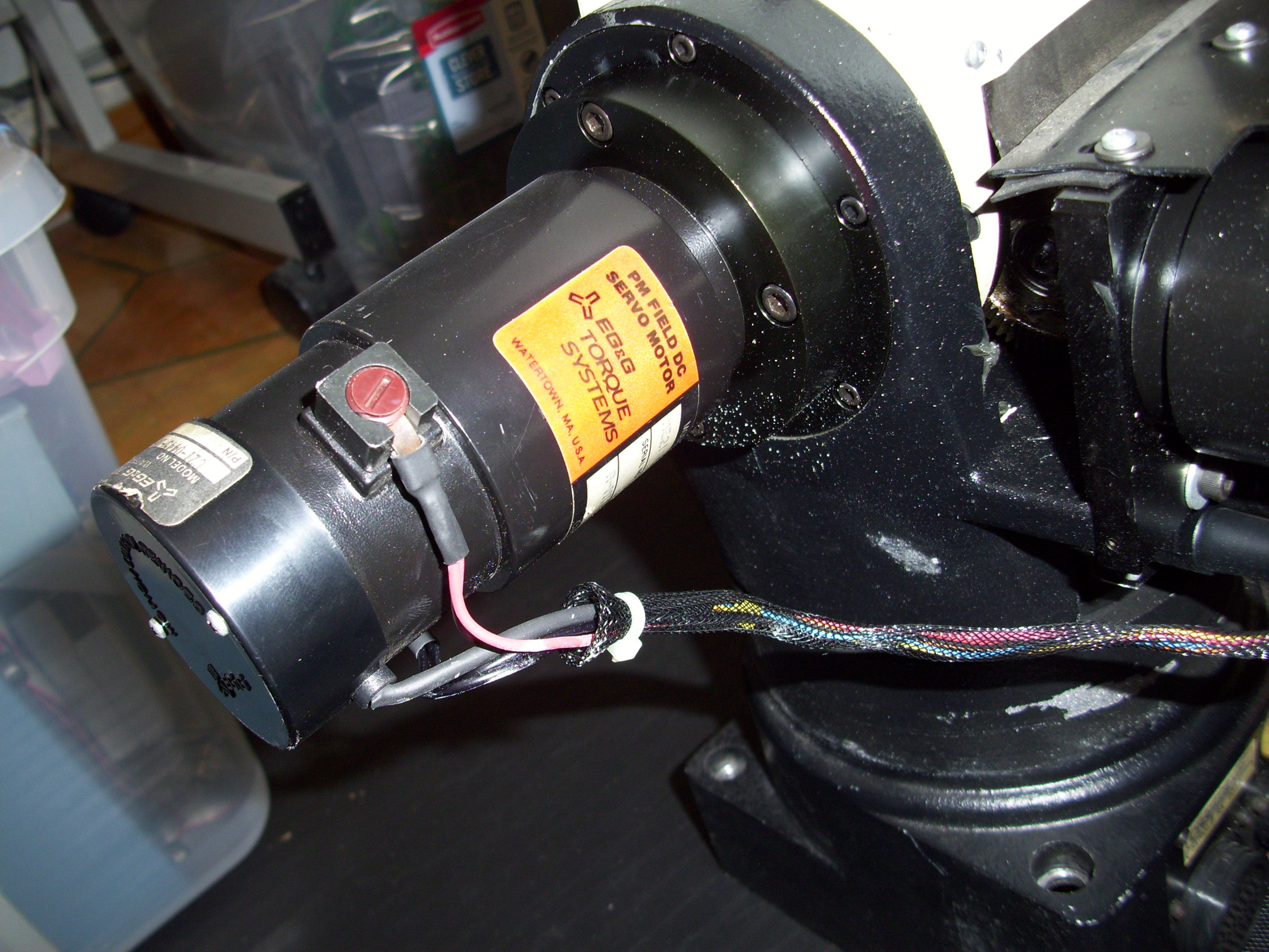
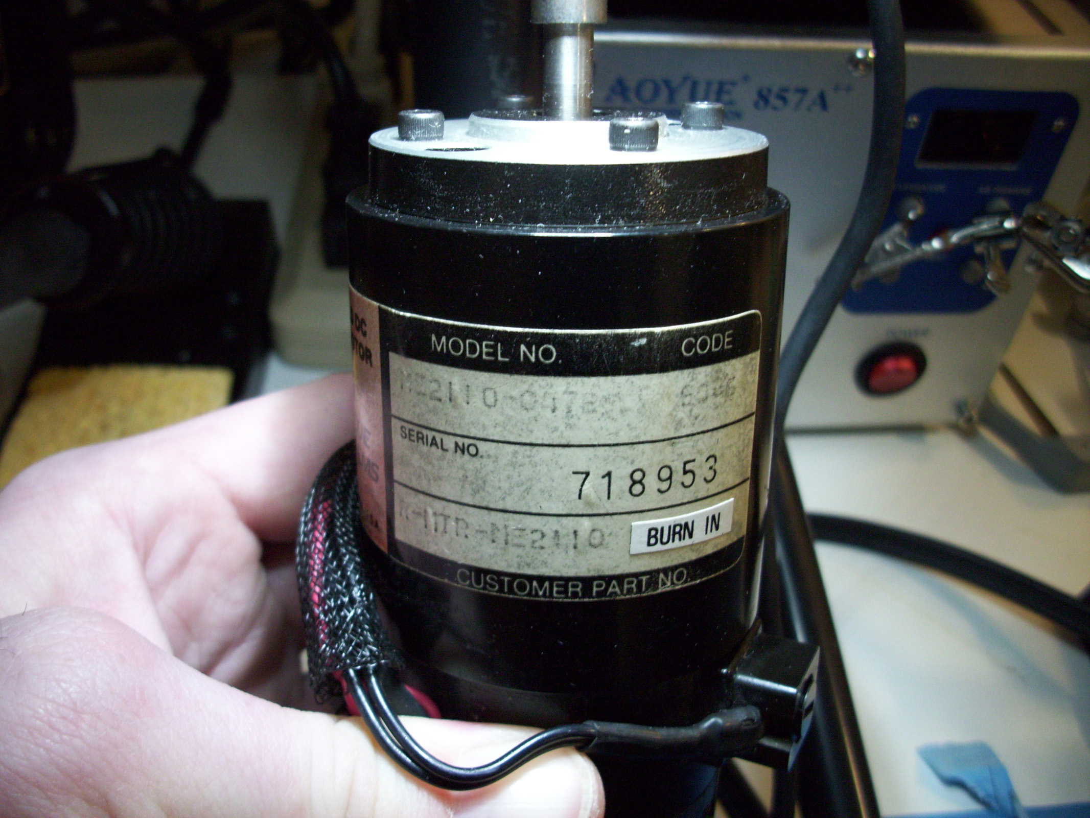
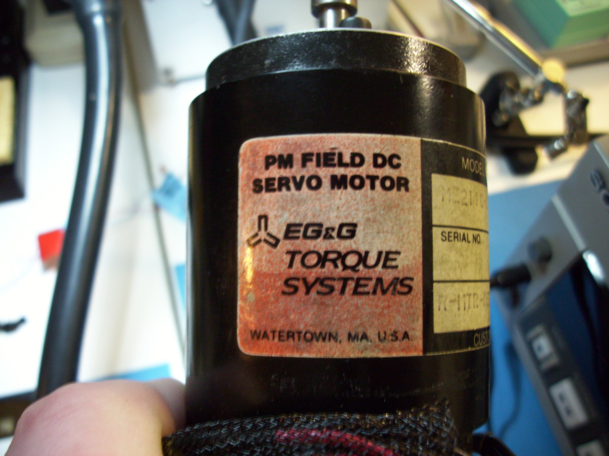
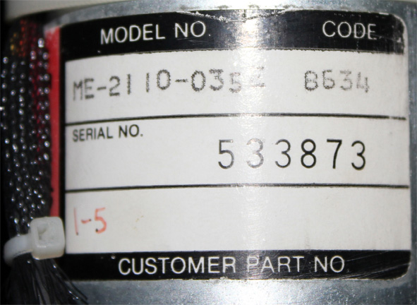
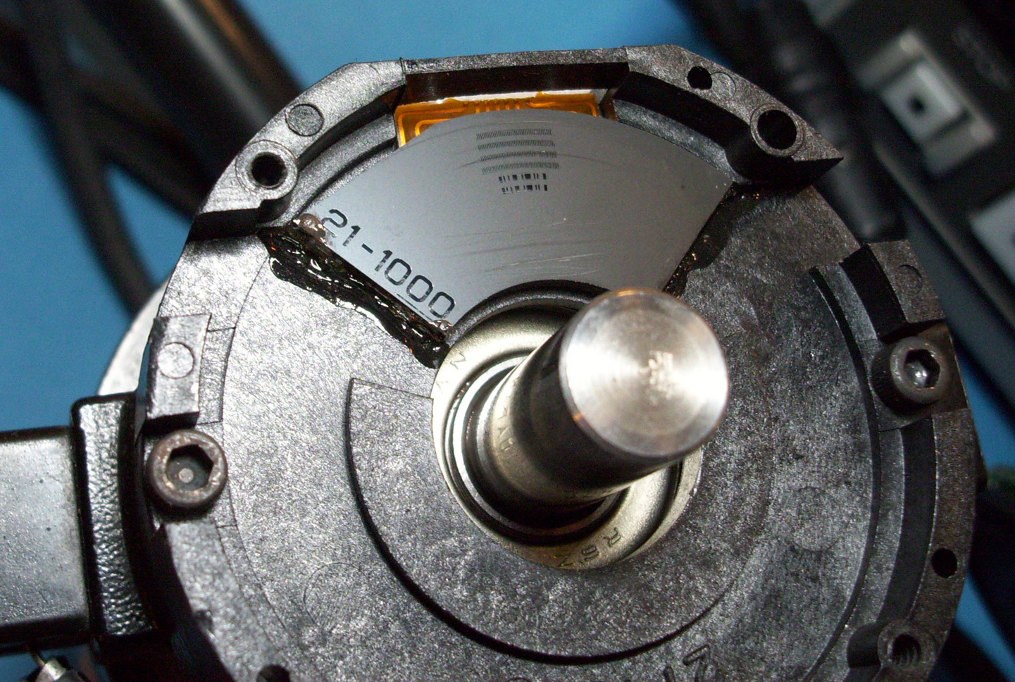
CRSPLUS Robot- EG&G DC SERVO Motor & Encoder The CRSPLUS series robots use "EG&G TORQUE SYSTEMS - PM FIELD DC SERVO MOTORS". This company is now called "Torque Systems" I believe. (http://www.torquesystems.com) The Model Numbers for the CRS PLUS Robot Stock Motors are marked as "ME2110-047E".
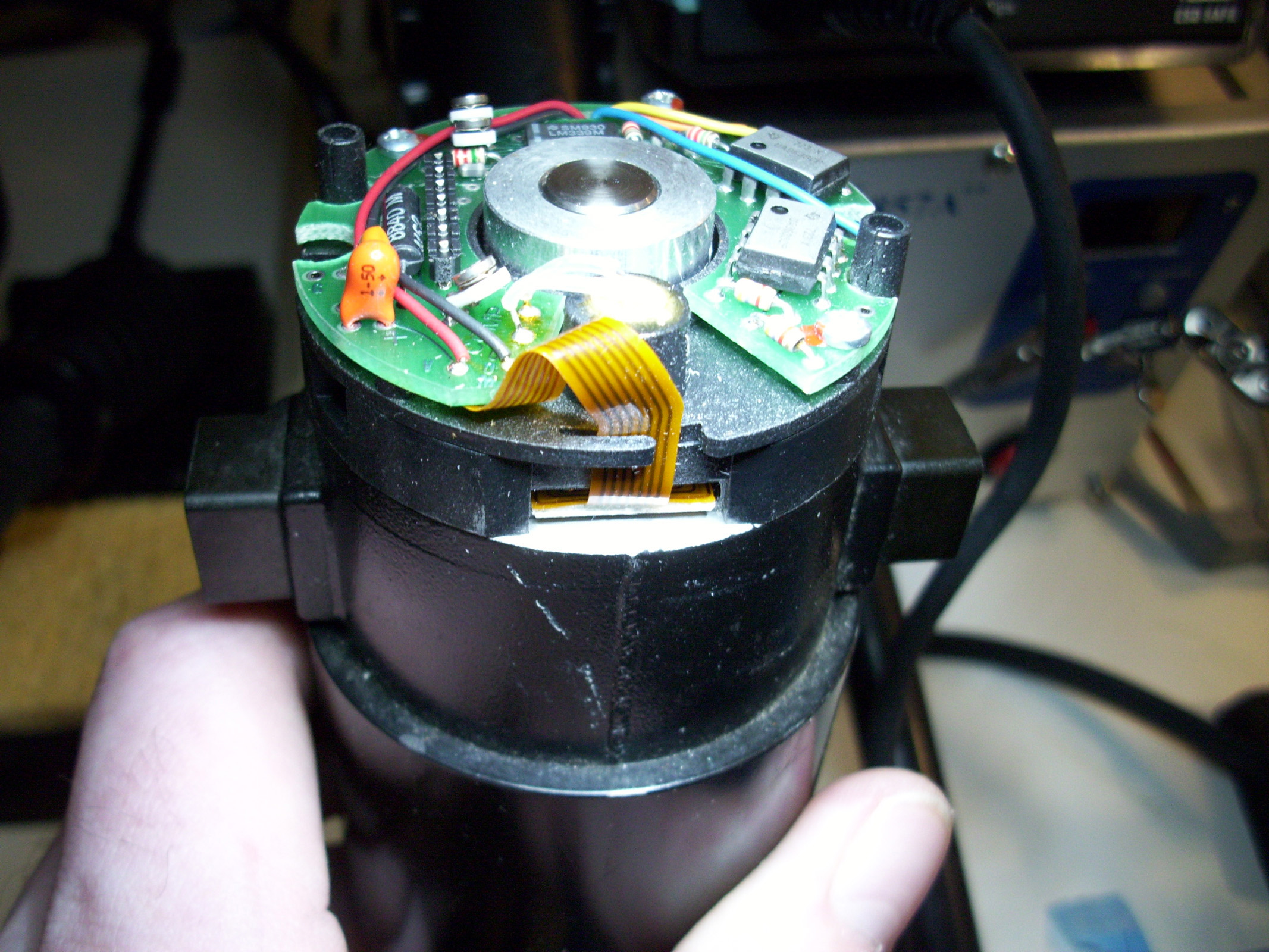
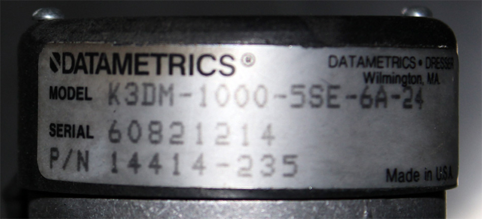
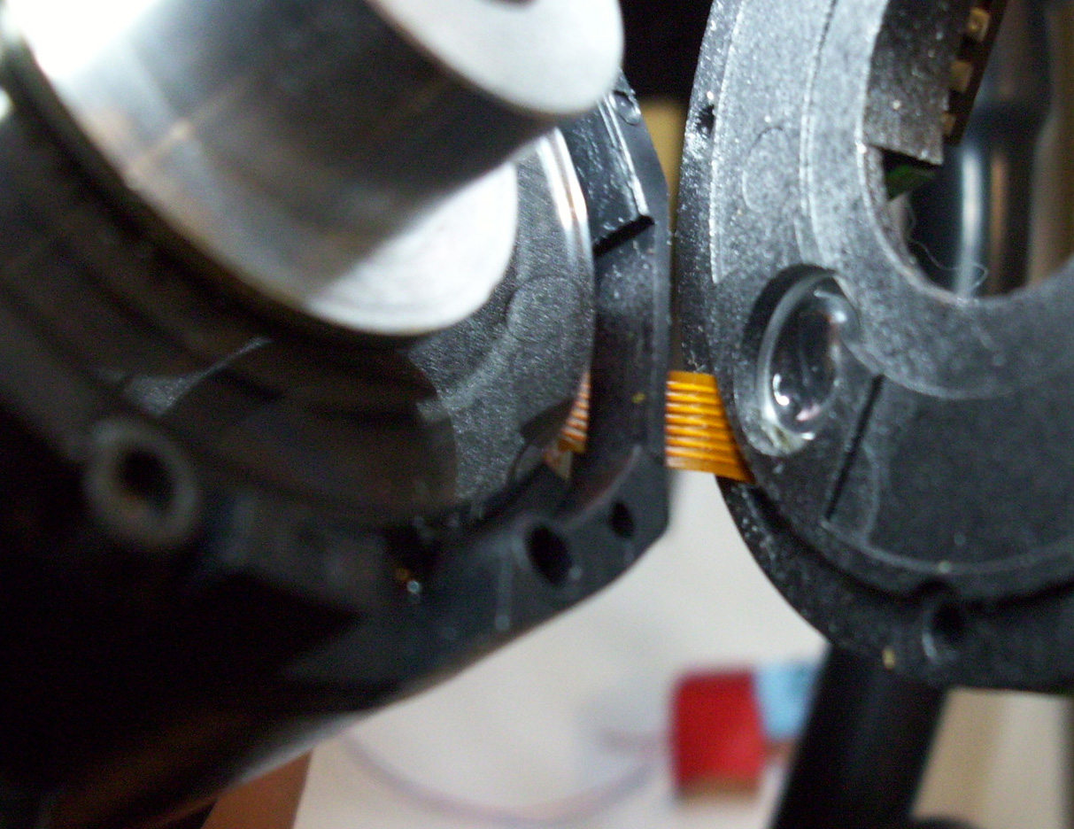
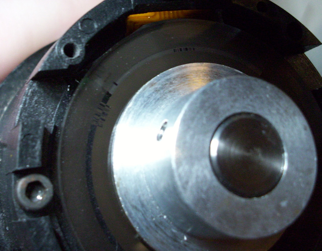
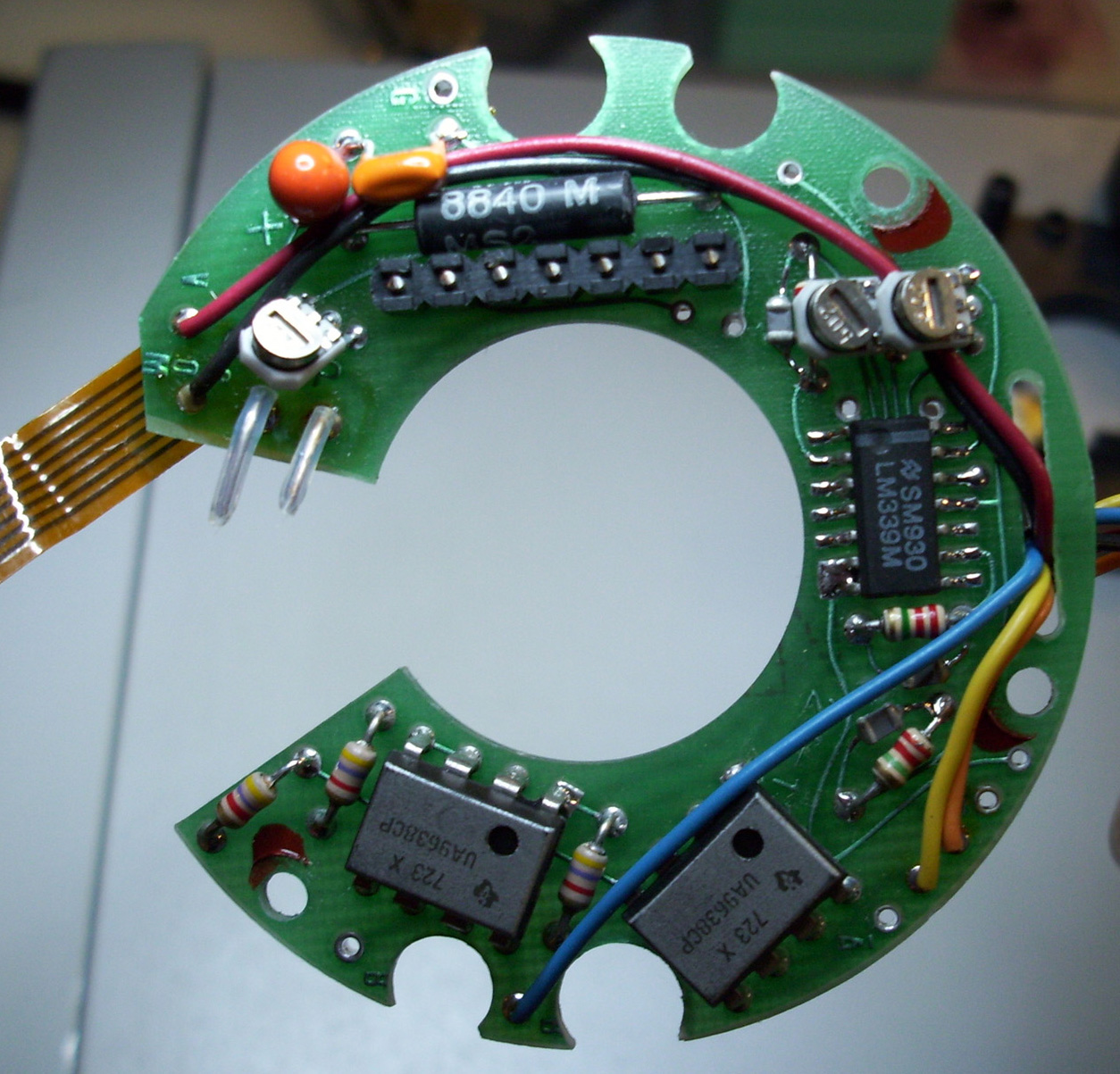
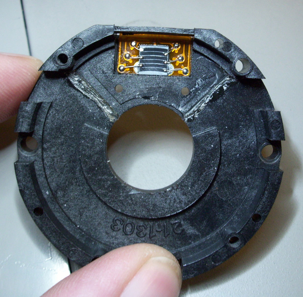
The Encodes are marked with the Model Number "C21-0445-DM-1000". These are 1000 count Incremental Optical Encoders by the company Datametrics. An alternative substitute Encoder is the 1000 Count "DATAMETICS" brand encoder Model # "K3DM-1000". A substitute DC Servo Motor is the "TORQUEMASTER 2100 Series" motors available from the Torque Systems website.
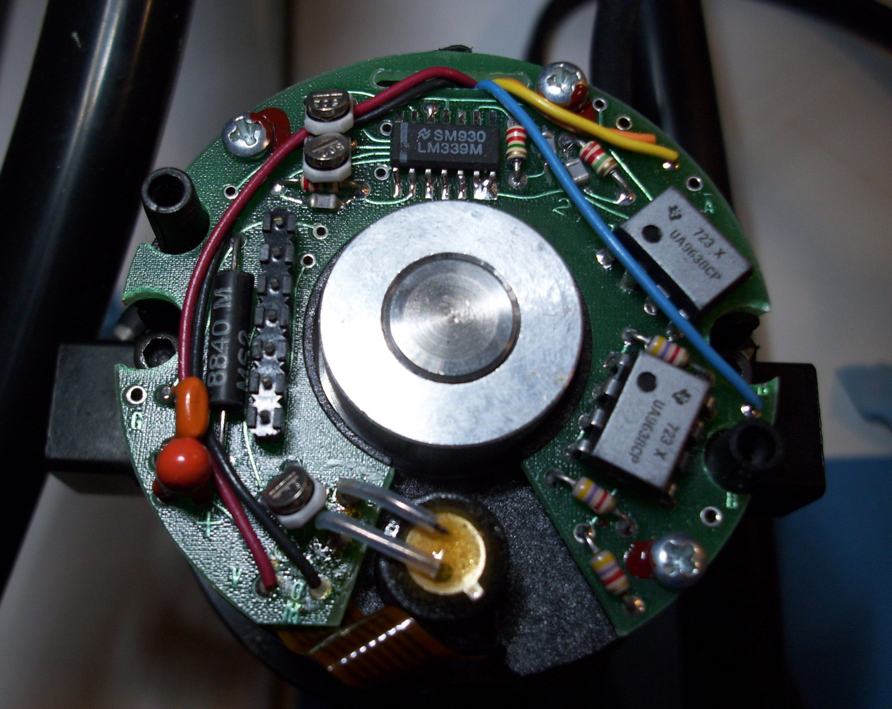
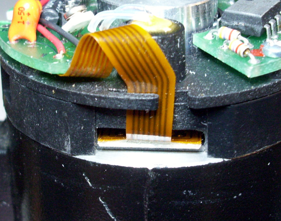
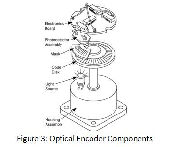
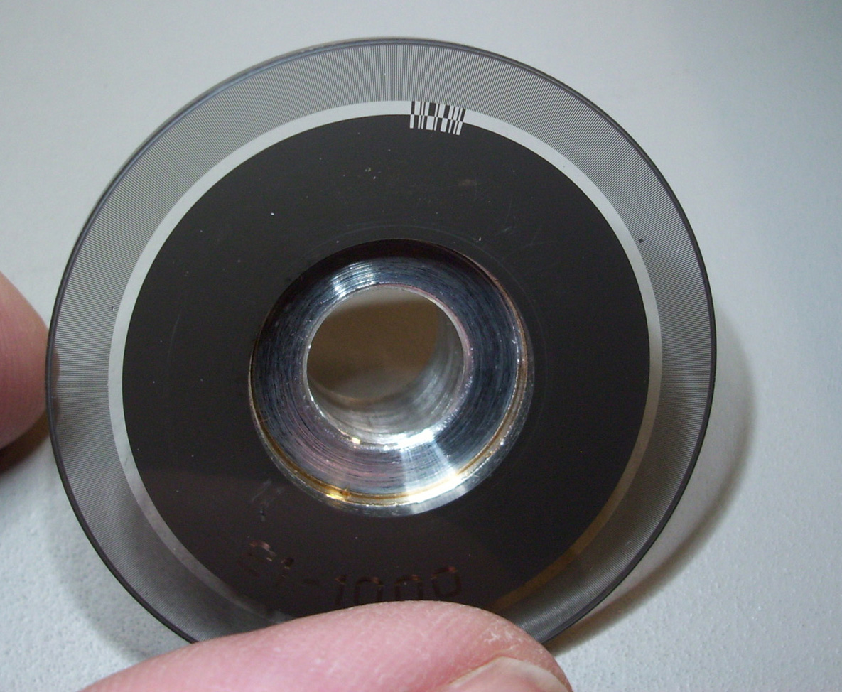
The Encoders Explained Incremental Optical encoders are sensors capable of generating digital signals in response to rotary movement. They are employed to convert the rotary movement into electrical signals and to obtain position and speed measures. The encoder generates a signal for each incremental change in position . In conjunction with mechanical conversion devices, such as rack-and-pinions, measuring wheels or spindles, incremental encoders can also be used to measure linear movement. With optical encoders, a grating disc made of metal or glass associated with a mask interrupts an infrared beam emitted by a transmitting gallium arsenide diode.
The number of gratings (increments ) determines the system ‘s resolution , ie . the number of increments per rotation. Every time the infrared beam is interrupted, this is registered by a receiver and then processed electronically.
To make the detection less sensitive to the light level, the receiver uses a differential measure between two photodiodes: one lighted and the other masked. The result is a square wave output signal as shown in the images below.
Two shifted photosensitive diode arrays deliver squared signals ( A and B) in quadrature. The Phase shift (90°) of signals A and B makes possible to determine the direction of rotation. In one direction, during the rise of signal A, signal B is equal to 1. In the other direction, During the rise of signal A, signal B is equal to 0.
The Z or signal zero comprises only one transparent window delivering one signal with a full revolution of the motor shaft. This signal is gated in synch with signals A and B. This zero signal determines a position of reference and allows re initializing of the system at each turn.
CRSPLUS Robot System User & Technical Manuals The Following manuals are not for this system, however they may assist you if you have nothing else. If you do have any Manuals / Software for the A150 or A250, A251 Robot systems,.... PLEASE CONTACT ME RIGHT AWAY!!!!:) or Join my "CRS Robotics" Yahoo Group at the Link below.
"SRS-M1" Manuals SRS-M1 TECHNICAL MANUAL (.Zip Archive Approx. 40Mb) SRS-M1 TUTORIAL MANUAL (.Zip Archive Approx. 10Mb)
"SRS-M1A" Manuals SRS-M1A RAPL Programming Manual (.Zip 87Mb) SRS-M1A Service Manual(.Zip 74Mb) SRS-M1A IBM-PC_Host_Interface (.Zip 40Mb) CRSPlus Digital I/O Expansion Module (.Zip 14Mb) SRS-M1A APPENDIX B and G [Technical Manual] (.Zip 33Mb)
Miscellaneous CRSPlus Manuals CRSPlus - Controller Internal Harness Wiring (.zip) CRSPlus - LOADHEX and SAVEHEX Commands (.zip) CRSPlus - Replace Serial Device Driver (.zip) CRSPlus - ACI Interface Library - Chapter 1 (.zip) CRSPlus - MODULE Descriptions - Chapter 2 (.zip) CRSPlus - ROBCOMM-II V2.0 Software Help-File (.Zip) "A150 & A250" Manuals I just recently got a hold of some Documentation from the CRSPlus A150 Technical Manual. The A150 Robot system is very similar to the M1A system. In Fact the M1A, A150 and A250 all use the same Motherboard. The A250 controllers use the enhanced Stand-alone Motor Driver cards, compared to the M1A and A150 that use the Standard Driver cards. The A150 Manual contains several references for both the 150 and A250 Robot systems. See the Links below for the Table of Contents and Chapters 5,7 & 8 from the A150 Technical manual. Eventually I hope to find the remaining chapters and share them here. Every little bit helps. :)
http://www.digital-circuitry.com/FILES/TOC_CRSPlus_A150.zip http://www.digital-circuitry.com/FILES/A150_Chapter5.zip http://www.digital-circuitry.com/FILES/A150_Chapter7.zip http://www.digital-circuitry.com/FILES/A150_Chapter8.zip
-=CRS ROBOTIC ARM YAHOO GROUP =- Please Join my CRS ROBOTIC ARM Yahoo Group! Let's all connect and share our Resources to get our CRS Robots up and running. http://groups.yahoo.com/group/CRS_ROBOTIC-ARM_GROUP
|
||
|
||