Current Time:


-= HOME =-

-= BLOG =-

-== BIO ==-

-=CONTACT=-

-=MY LAB=-

-=CHIPPERY=-

-PROJECTS-

-= LINKS =-

-= VHDL =-

-=YouTube=-


Gerry's Current Research & Development Projects

Programmer  -= SEGA =-  -= ALTERA LP6 =-  -= NKK SMART DISPLAY =- 


Gerry's Completed Projects

GAME GEAR    -== SMS ==-   GAME BOY   -== NGPC ==-   -=VHDL VGA PONG=-   -== LCD DISPLAYS ==-  

YOU ARE VIEWING THE NINTENDO GAME BOY PAGE

Please Join the GameBoy Electronics Yahoo Group!

http://groups.yahoo.com/group/GAMEBOY_Electronics/

A fantastic resource and a way for us all to connect and work together at building our very own Gameboy Electronics Projects.

Join Today !!


D.I.Y. 512Kb NINTENDO Game Boy Flash Cartridge

Below you will find links to my Youtube Channel , a PDF procedures guide and also Images of the completed flash cartridges.


For a detailed overview on Memory interfacing and Memory Mapping concepts used by the Nintendo Gameboy & Sega GameGear.....

Click the Link Below:

http://www.digital-circuitry.com/8-bit_Memory_Mapping.htm


-=My Instructional Videos for this Project=-

*** UPDATED MAY 2012 ***

My YouTube Channel : http://www.youtube.com/user/NLEproGUY

.Below is my 5 Part Instructional video For this Gameboy Flashcart to accompany the PDF procedures guide.

PART #1:


PART #2:


PART #3:


PART #4:


For your GB backup ROMs visit: http://romhustler.net/roms/gbc


-=SOCKETS TO USE FOR YOUR FLASH CART=-

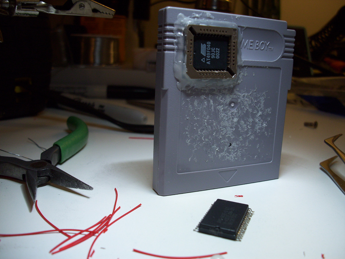
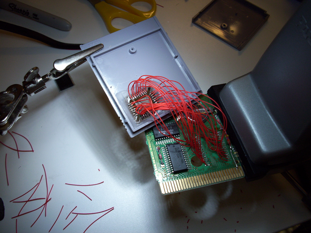
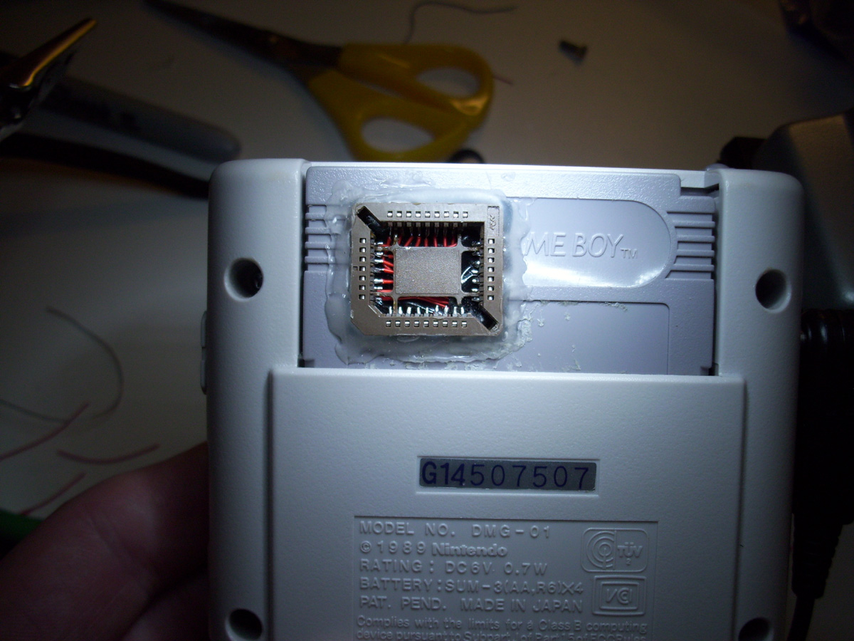
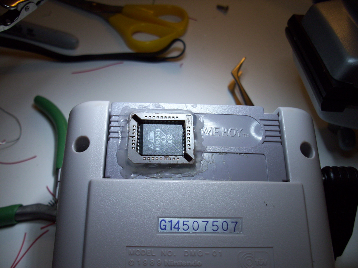
Just thought I would toss this in here as a option instead of using the Cheap PLCC32 plastic sockets....

The Standard PLCC 32 pin ROM sockets are not really meant to be used if you are going to be repeatedly removing the chip.

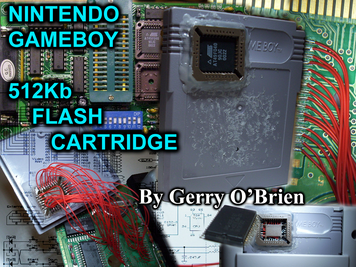
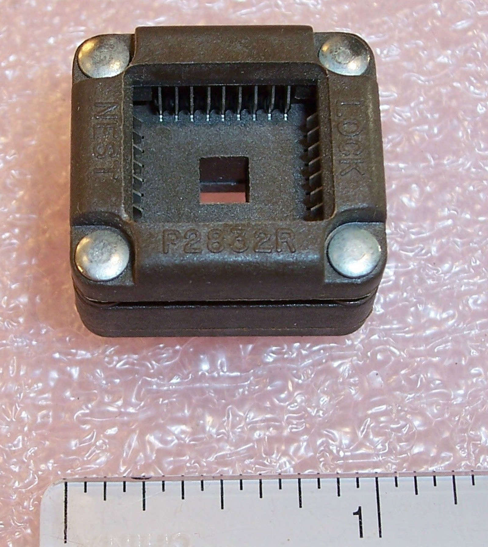
Now I know this might be a more expensive option, however if you are going to be repeatedly removing the PLCC chip for programming, I would suggest using one of these PLCC32 TEST "BURN-IN" SOCKETS from PLASTRONICS.

eBay Sale: http://www.ebay.com/itm/P2832R-PLASTRONICS-LOCK-NEST-32-PIN-PLCC-TEST-AND-BURN-IN-SOCKET-OPEN-TOP


This way there is Zero insertion force.....or extraction force for that matter.
You just simply push down on the sides of the socket...and the Pins inside are spring loaded and will retract
while you place or remove the chip from the socket......insert or remove with zero resistance.


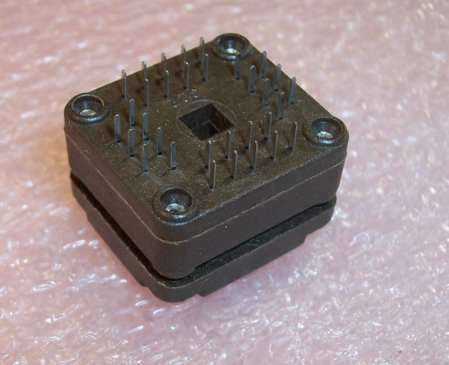
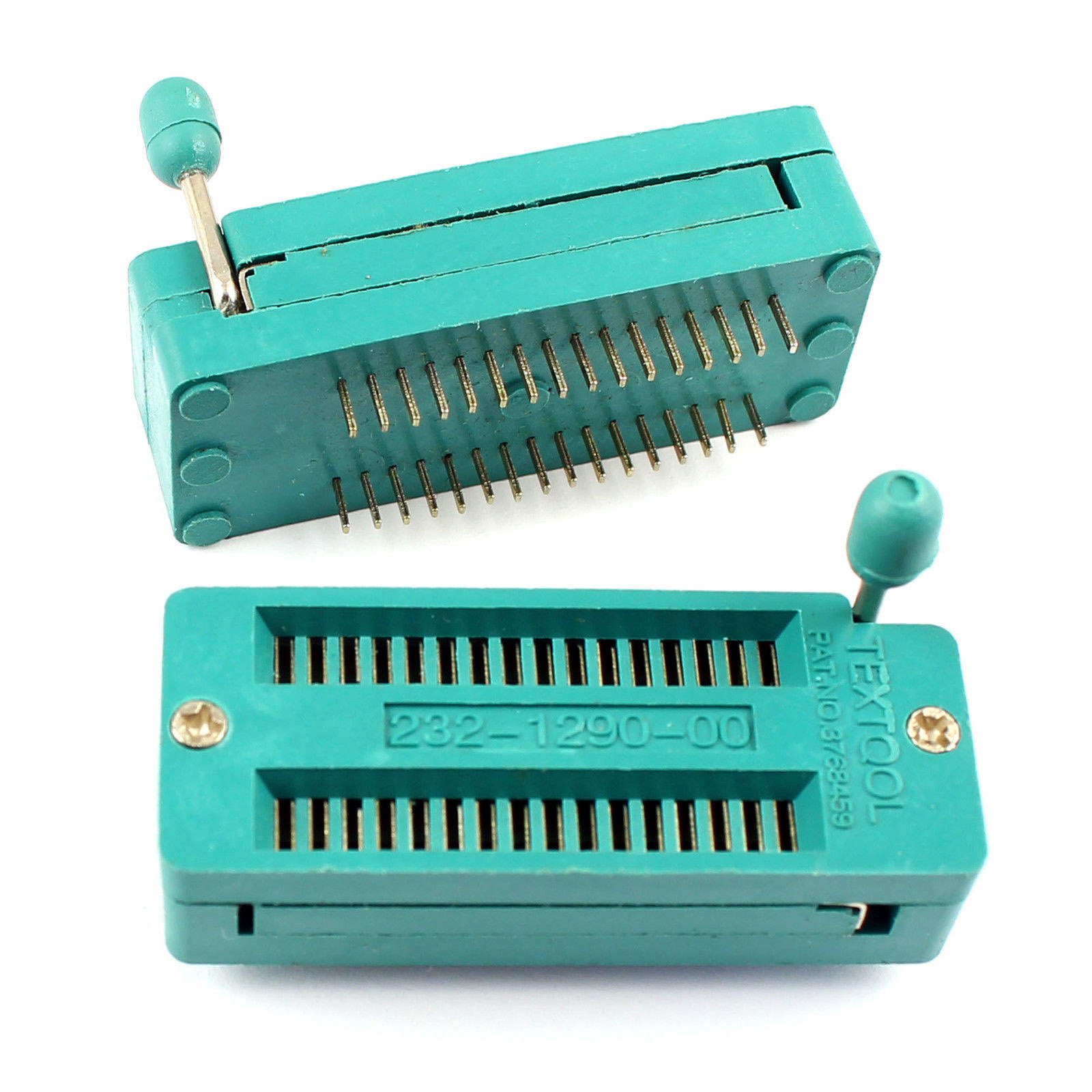
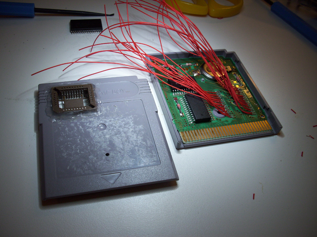
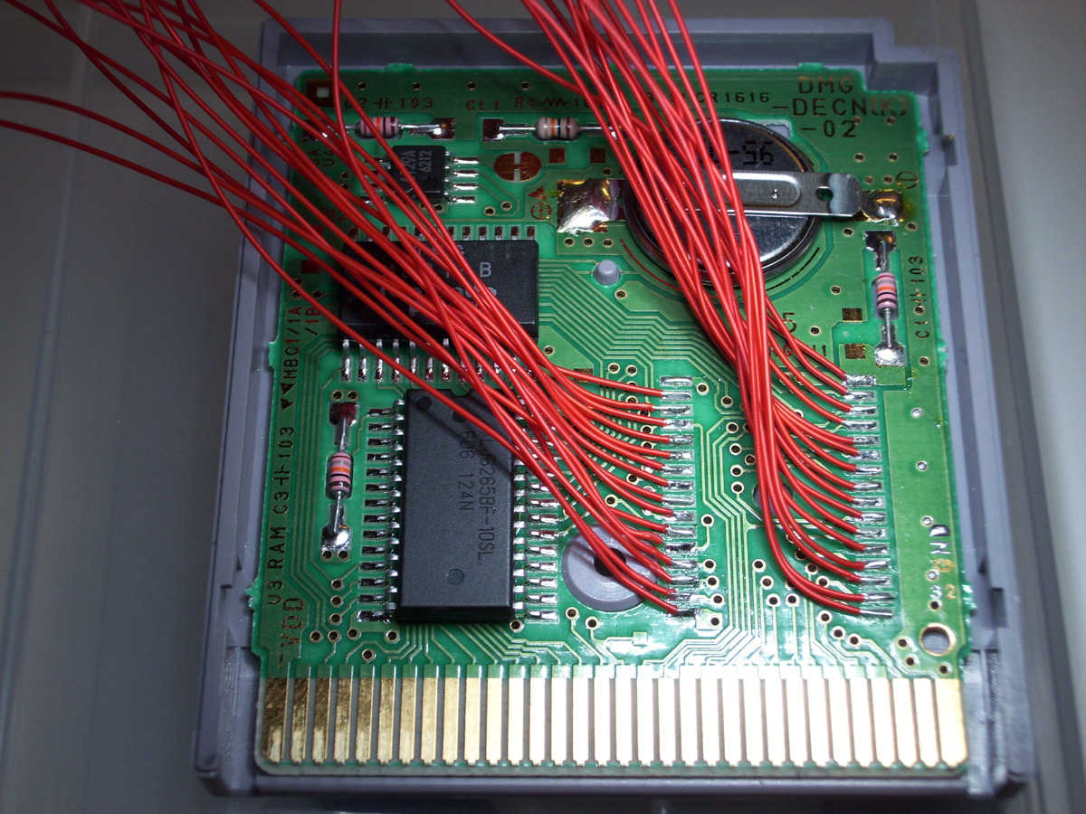
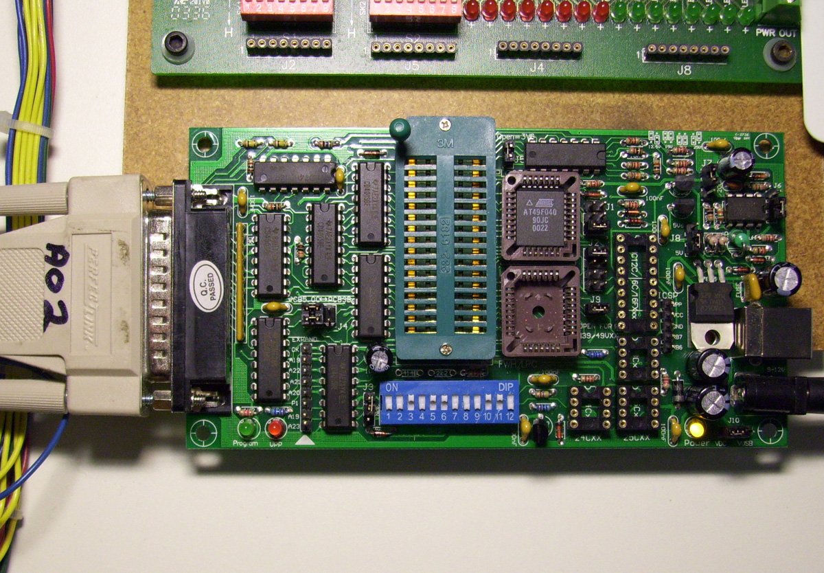
The other option as I will mention in the videos... and that is to just use the DIP version of the 4MBit Flash chip....and use a 32 Pin ZIF.
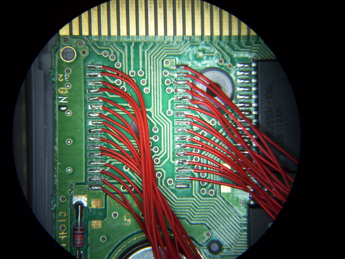
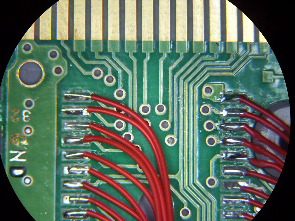
The pinouts for either the DIP or PLCC version of the AT49F040 are identical, so you just match them up accordingly when you are wiring up the socket to the cart PCB.

eBay Sale for 32pin DIP ZIF socket: http://www.ebay.com/itm/2PCS-32-Pin-Universal-ZIF-DIP-Tester-IC-Test-Socket


-=My "Step by Step" Procedures Guide

*** UPDATED AUG 2016***

"Step by Step" PDF Guide: Gameboy Flash cart - Step by Step Guide


-=My Gameboy MBC1 Flash Cartridge=-


For Further information on Gameboy related Eelctronics projects, see Reiner Ziegler's Website: http://www.reinerziegler.de/index.html

Hopefully the information I have posted here will help you all succeed in building your very own Nintendo Gameboy Flash Cartridges.

Soon enough you'll be up and testing your own custom code or custom games on the real hardware.


Lets get to it shall we?......... Assembly code anyone?


Kind Regards,

Gerry O'Brien


Please Join the GameBoy Electronics Yahoo Group!

http://groups.yahoo.com/group/GAMEBOY_Electronics/

A fantastic resource and a way for us all to connect and work together at building our very own Gameboy Electronics Projects.

Join Today !!