|
Current Time:
|
|
|
Gerry's Messy Electronics/Robotics Click the button below to go Back to the "CHIPPERY " section of my Lab
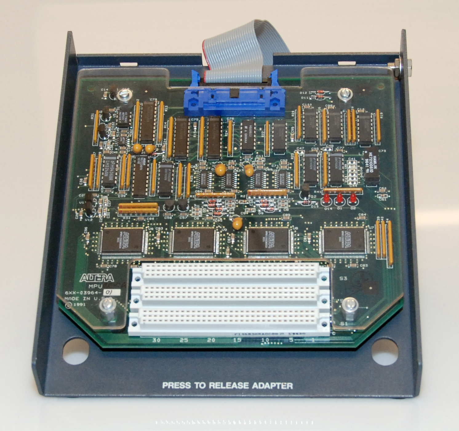
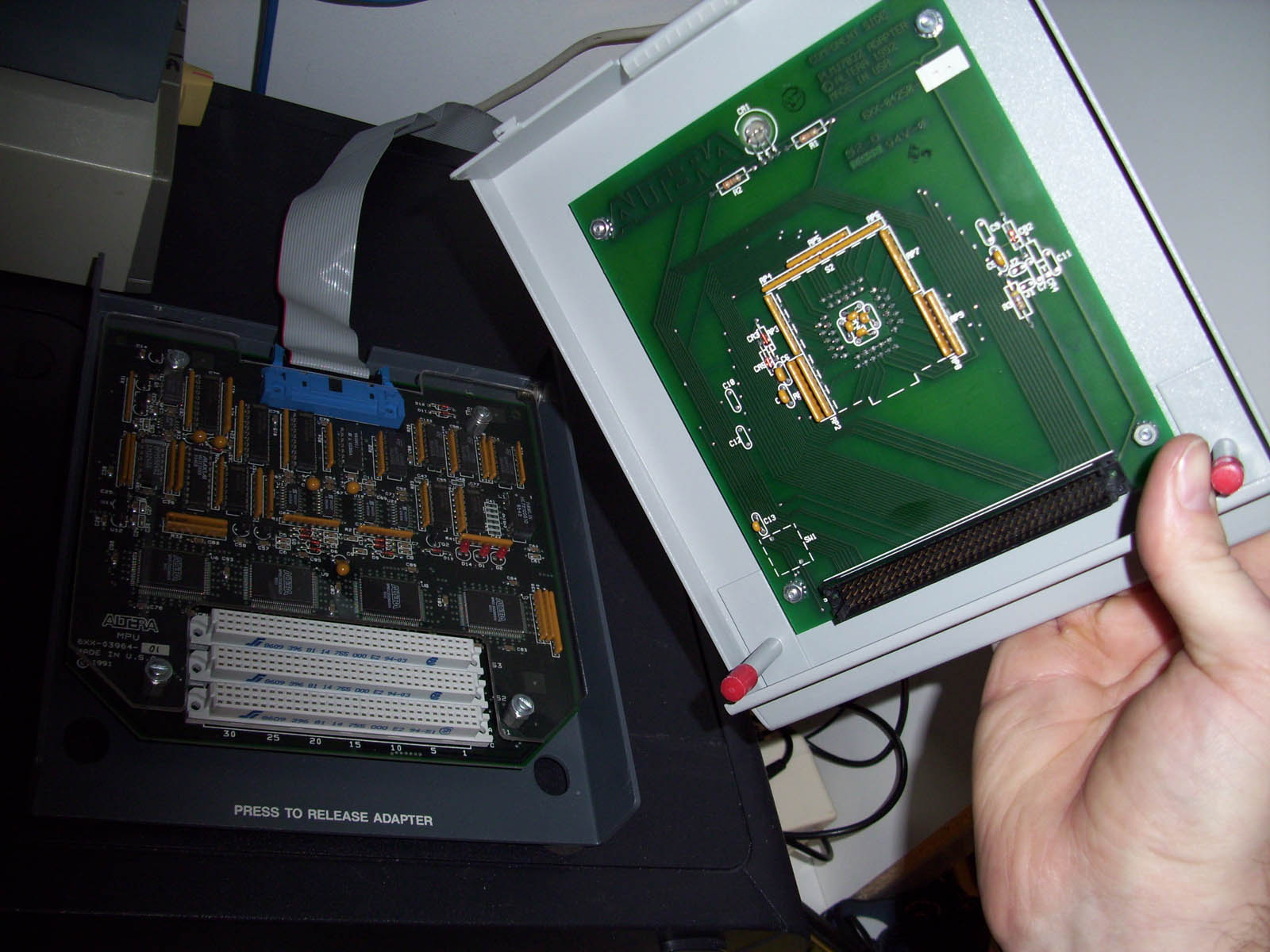
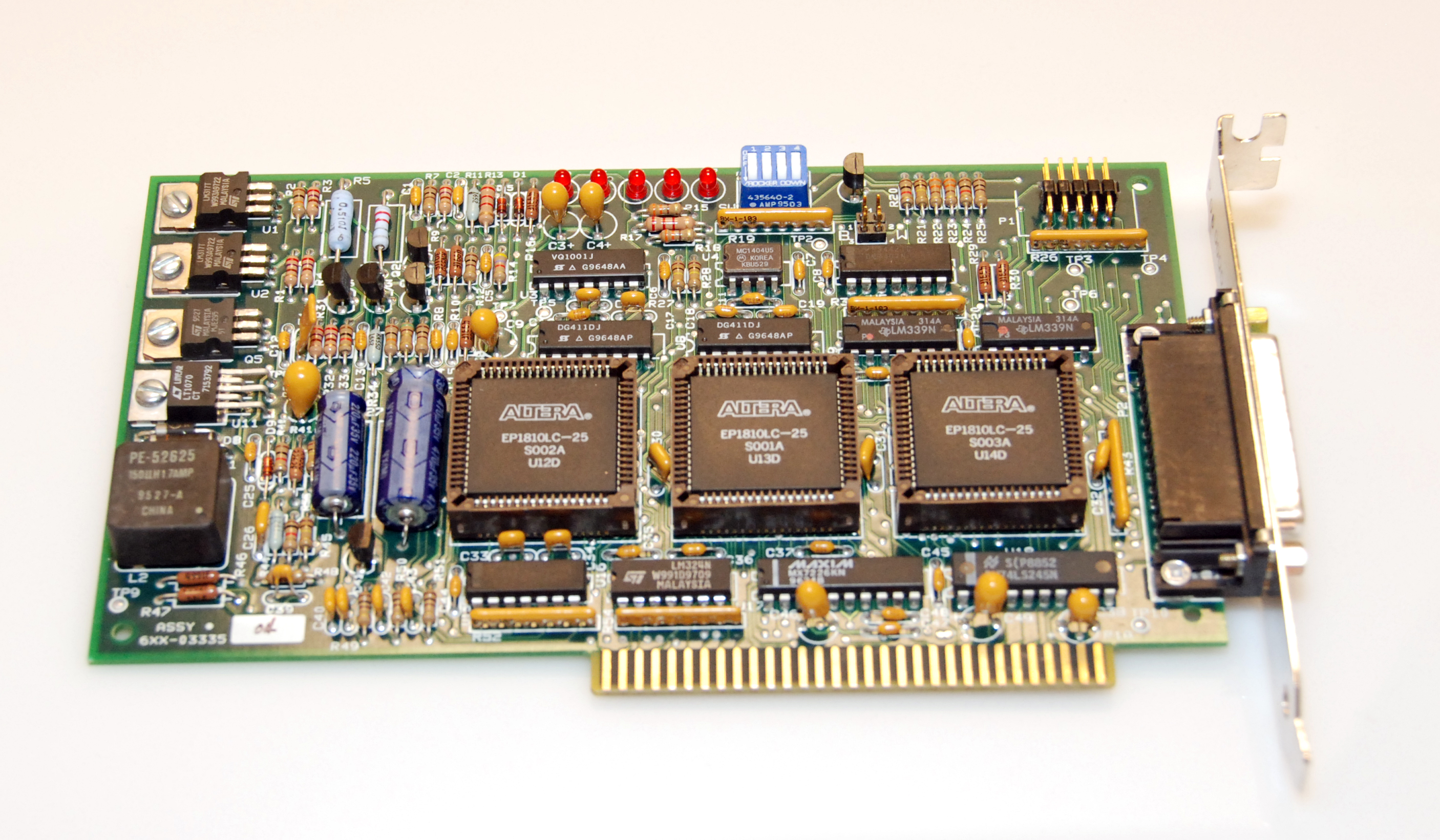
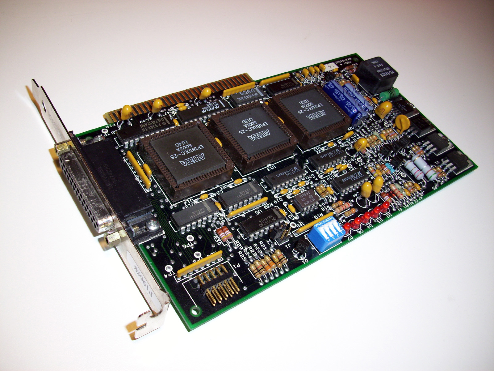
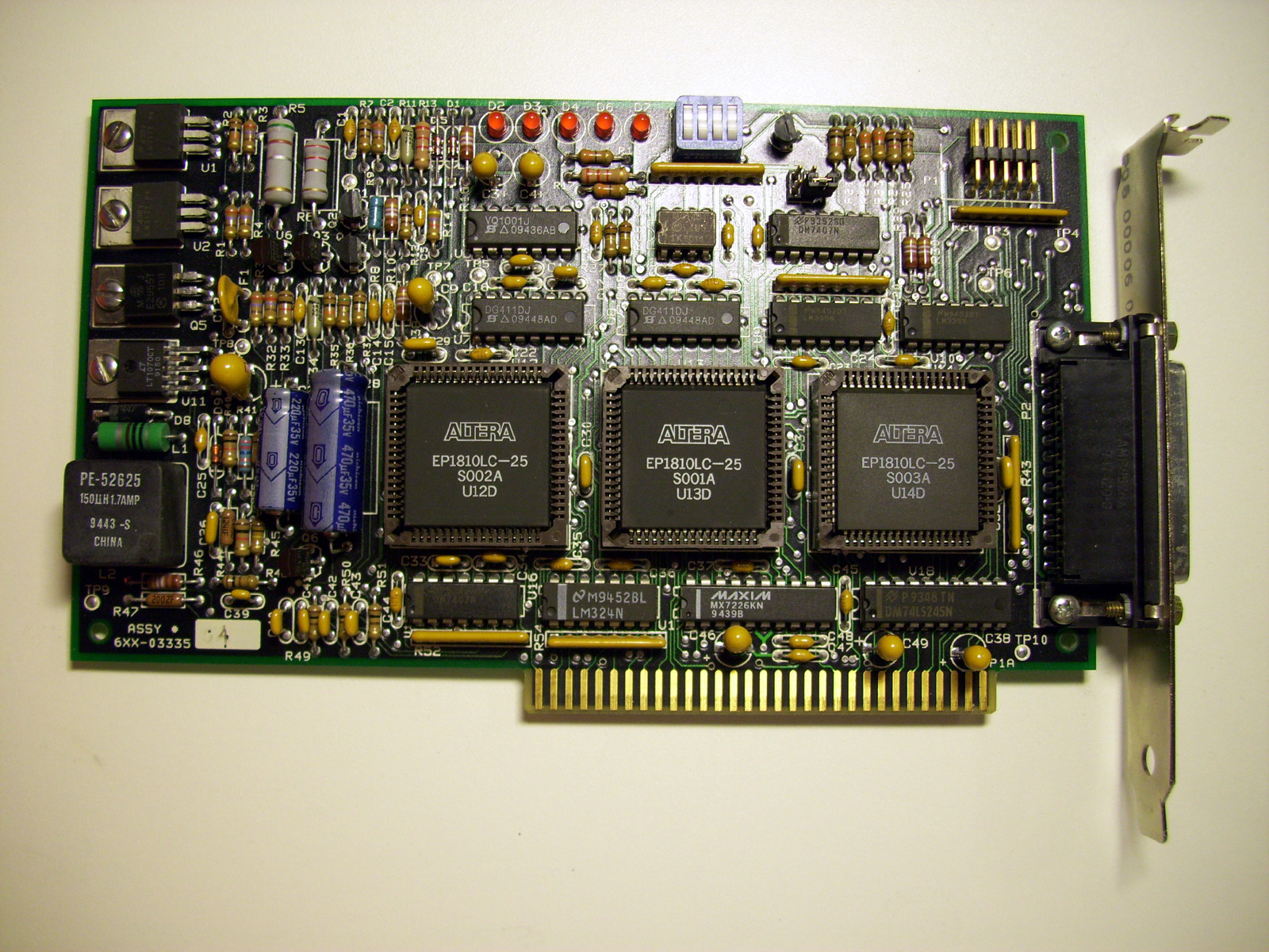
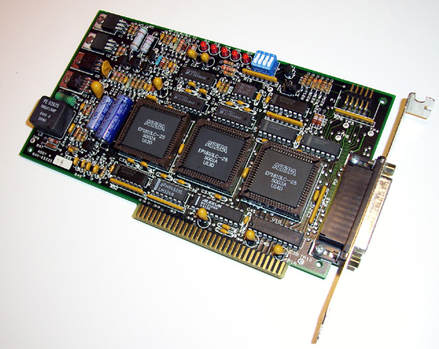
Altera Master Programming Unit Model PL-ASAP2 and it's accompanying LP6 Logic programming card. The Altera PL-ASAP2 Master Programming Unit, consists of three main components. The MPU Base module, the LP6 Logic Programming card and an Adapter which has a Chip Socket to accomodate Logic programming for your traget device.Shown below are the Base module and the LP6 Logic Programming card.
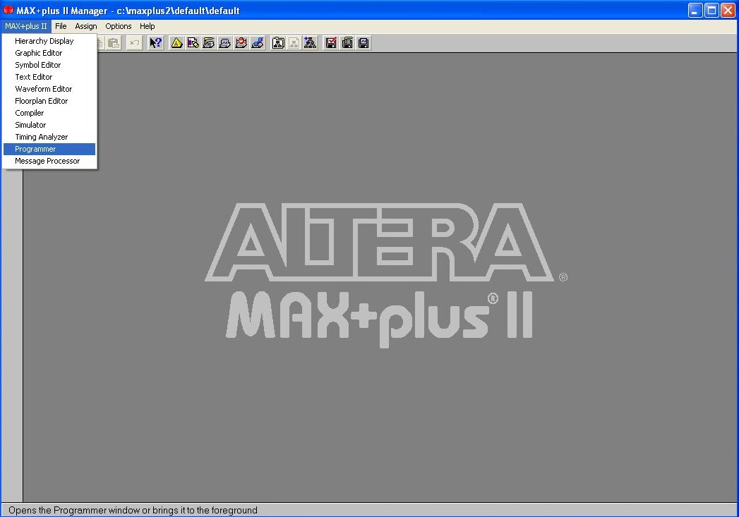
Altera MAX+PLUS II Software Several versions of the MAX+PLUS II software were released. The earlier Versions such as the Version 5.x release ran on a Computer PC using the DOS operating system and Windows 3.1 or an early version of Windows NT. Shown below is the Altera MAX+PLUS® II software GUI for Windows 98/2000 Operating system. The MAX+PLUS® II software is used with the PLE3-12/12A MPU and the PL-ASAP2 MPU with either the LP4/LP5/LP6 Logic Programmer Cards. For if you are Programming with the USB based Alera "PL-APU" Programmer hardware, The latest version of MAX+PLUS II V10.23 is recommended. However when needing to Program earlier classic components, or the Altera MAX 9000 & 9000A series components; with either the PL-APU programmer or the PL-ASAP2 programming system, the MAX+PLUS II Version 9.6 is recommended. This version of the software has the particular component libraries, for all of the MAX 9000 family components. From the EPM9320 model, all the way to the EPM9560.
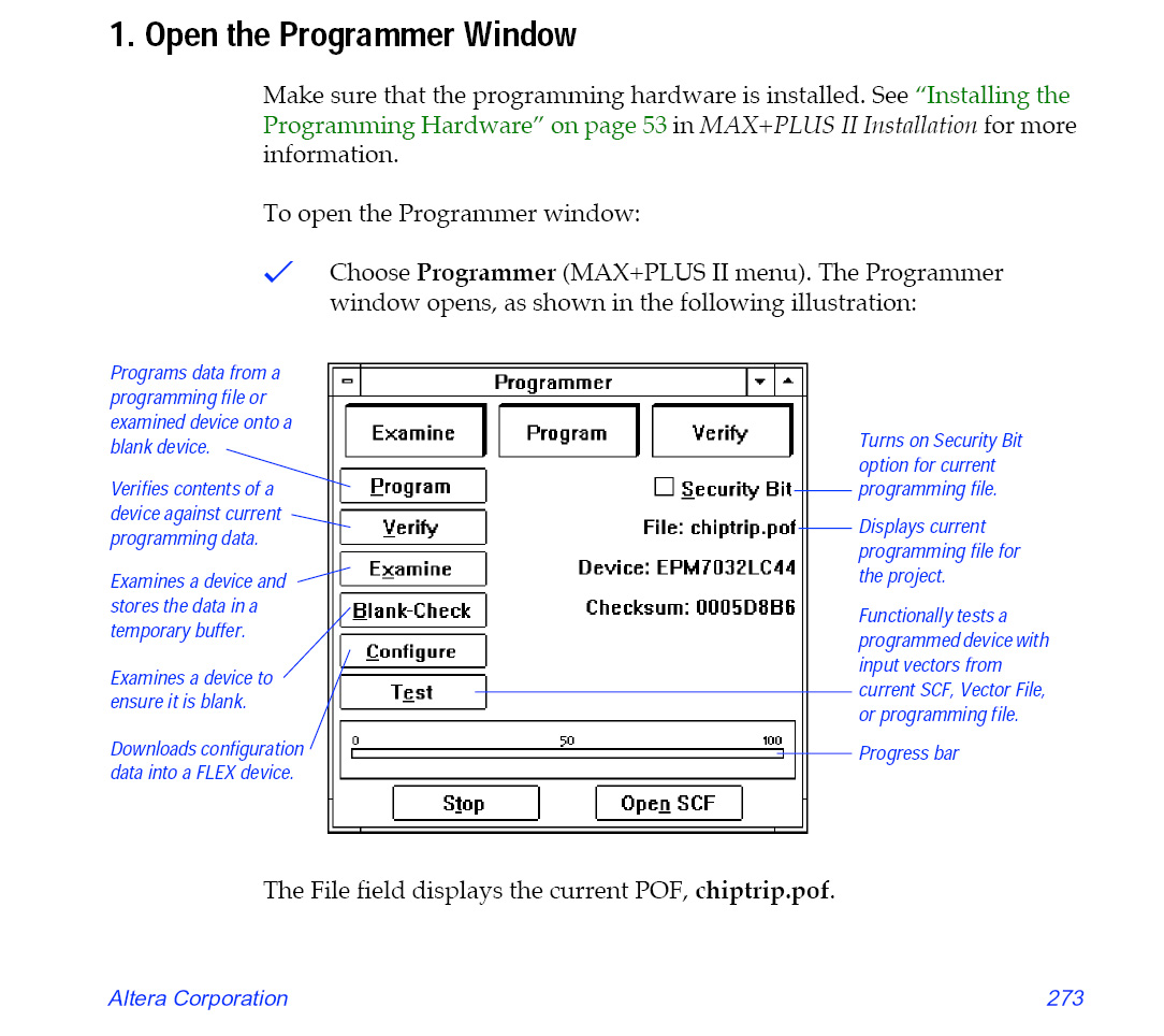
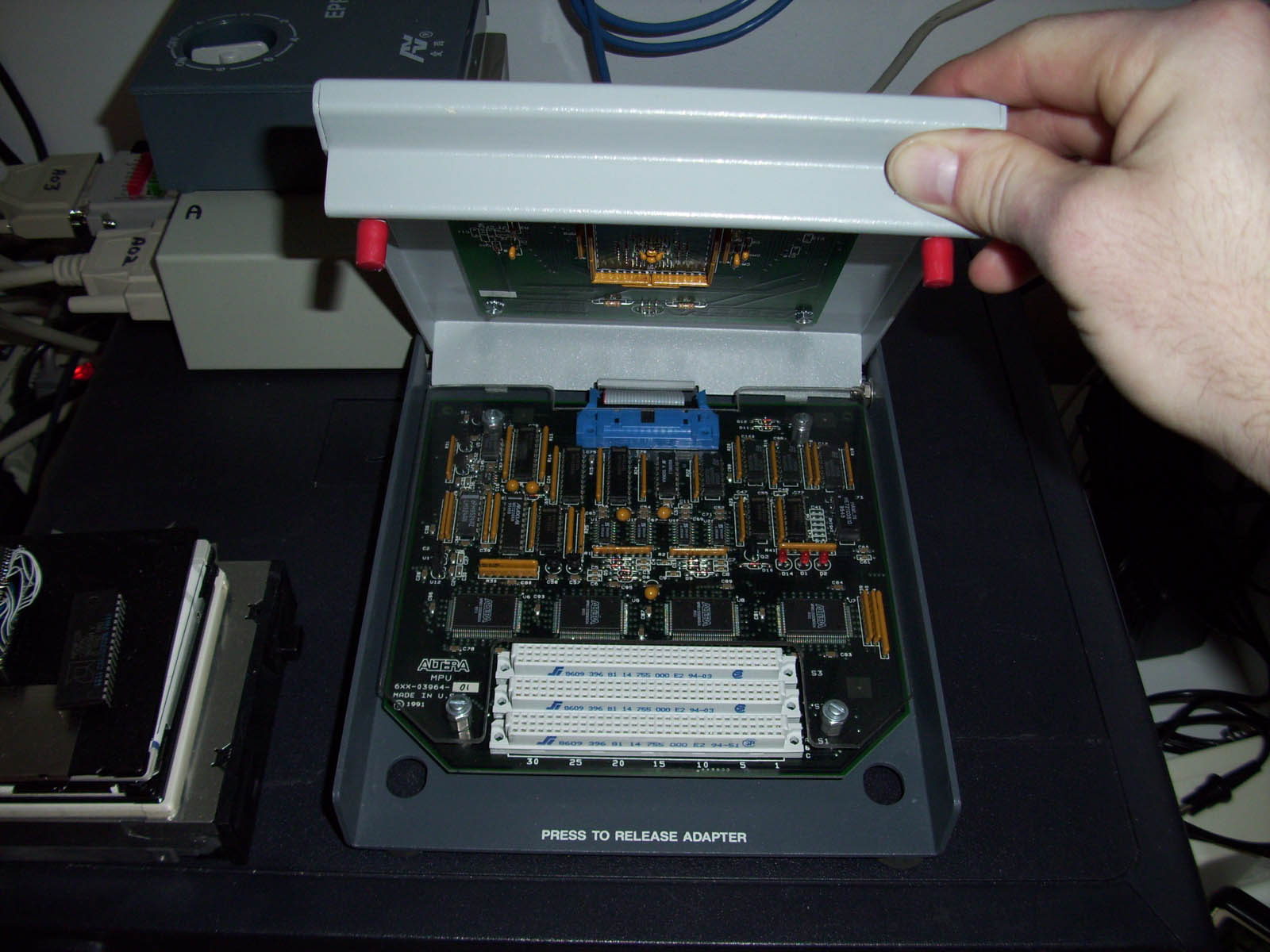
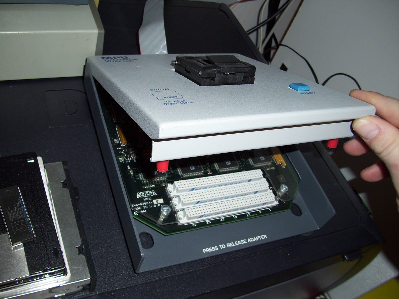
Altera MPU Base Module
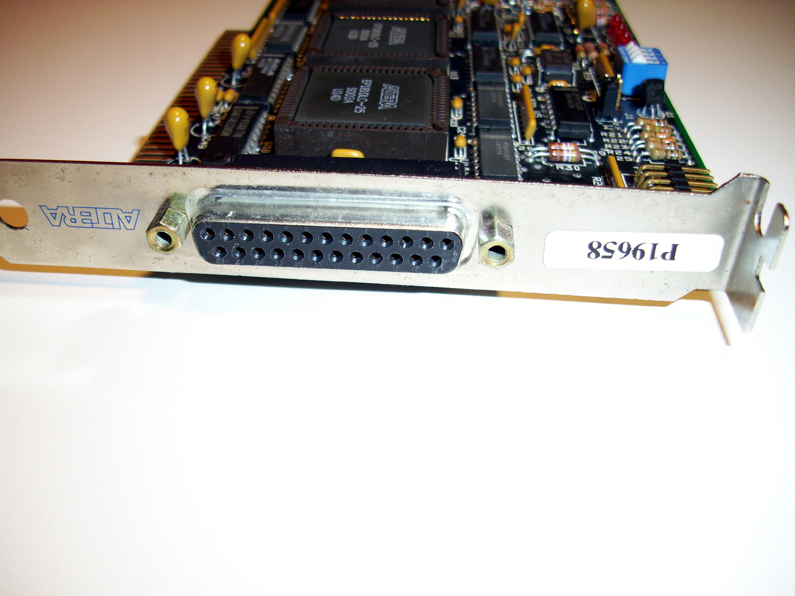
The base frame is made of a heavy steel which has been painted with a Gray paint through an Electrostatic painting process. Each adapter has also gone through this same process which gives the queipment a very clean professional look. The Base module has three female connectors which provide the interface between the Adapter and the base module itself. The Logic signals originating from the LP6 Logic Programming card (Shown Below), are fed through a Ribbon cable to the MPU Base Module. The Ribbon cable has a DB25 male connector which attaches to the LP6 Logic Programming card. On the opposite end of the Ribbon cable, lies an IDC male connector that connects directly to the MPU Base. See the Images above. Having a DB25 connector on the LP6 card, is actually one of the prime reasons these cards have come to be extreemly rare. When the PL-ASAP2 progamming units were released, the main consumers, where Enginners working for Large R&D companies as these programming units were quite expensive originally. As time went on, and the units became discontinued, some of the equipment was sold off or ended up being put away into storage. Usually what ended up happening, was as new Enginners and Technicians were hired, and the computer towers that housed the presious LP6 cards, where brought out to be used as regular office PC. The LP6 cards were frequently mistaken for an LPT Printer Port interface card, all due to the DB25 Connector. Usually when the Technician couldn't get the Printer to work, the cards were tossed or thrown into a parts been to be sold off for scrap or junked into the garbage. YIKKKEESSS!!! The thought of that just Hurts! If only altera had chosen to use a more expensive looking connector more of these units might have been saved.
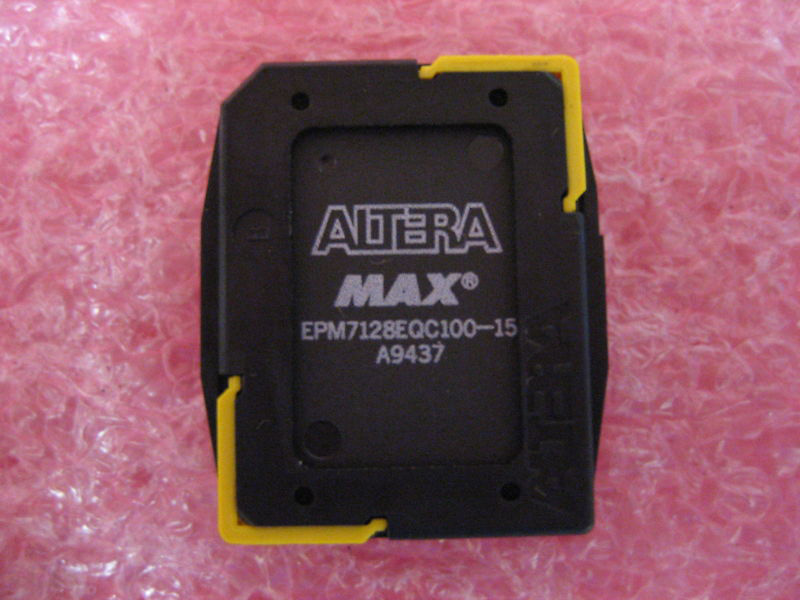
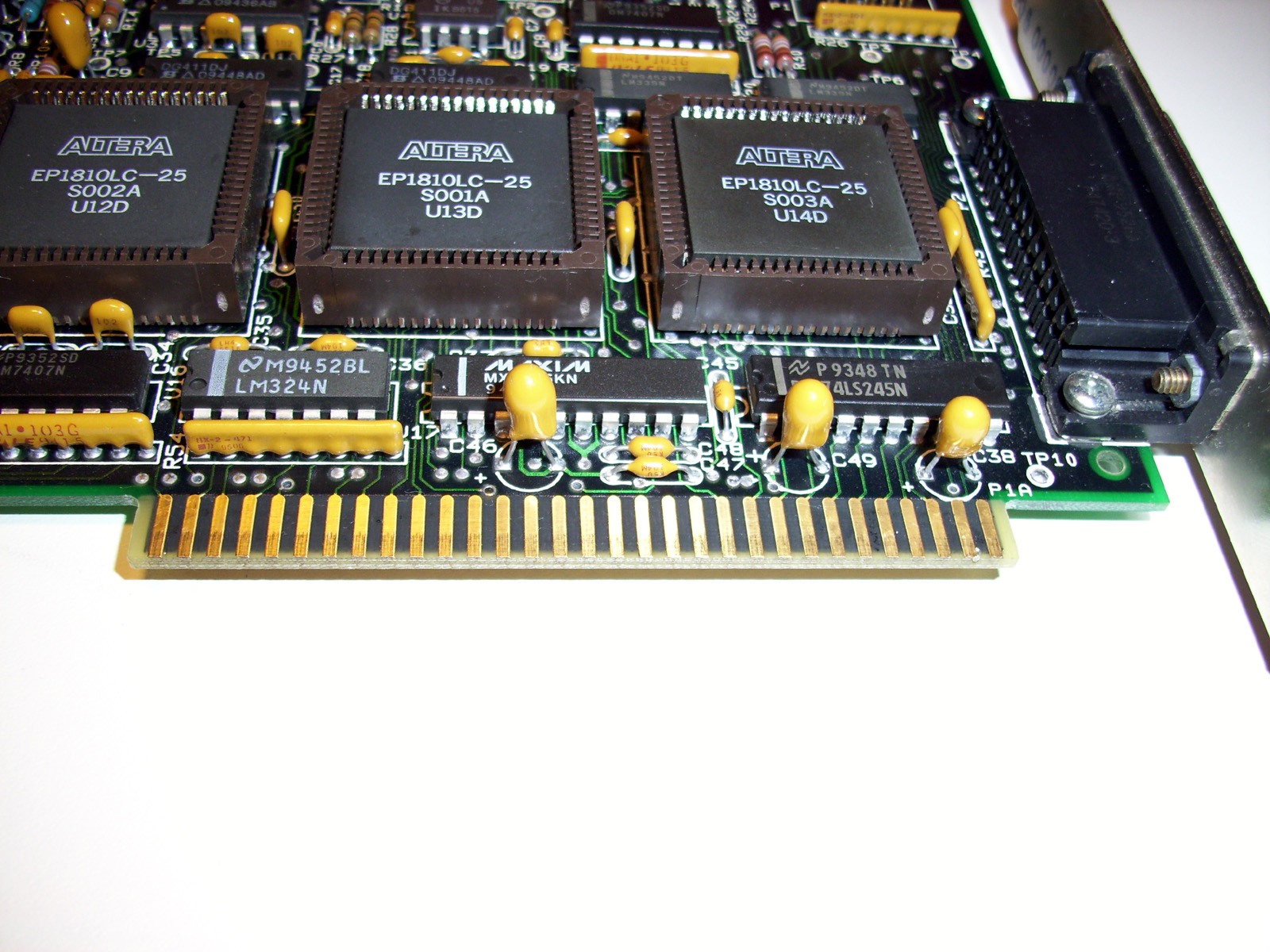
Altera Plastic QFP Chip Carriers
You can see one of the Altera Plastic Carriers in the center image above. Altera CPLD Chips come in various package formats. For devices of 100 Pins and over, the chips come in special plastic carriers. The carriers not only protect the chips pins from accidental damage, but also provide protection while the device is being programmed or is being shipped to the customer. Some models of adapters (PLMQ & PLMR) for the Master programming unit are designed to have the chips inserted with the protective Carriers on the chip. Various MPU adpters will have the Suffix "NC" at the end of the adapter Model#, indicating it is a "NO CARRIER" type of adapter. You can read specific information on Altera QFP Carriers from the Altera Datasheets listed below: "QFP Carrier & Development Socket Datasheet" & "Ordering Information Document" http://www.digital-circuitry.com/ALTERA_QFP_Carrier_&_DEV_Socket_Datasheet.zip http://www.digital-circuitry.com/ALTERA_DEV_Hardware_Ordering_Codes.zip
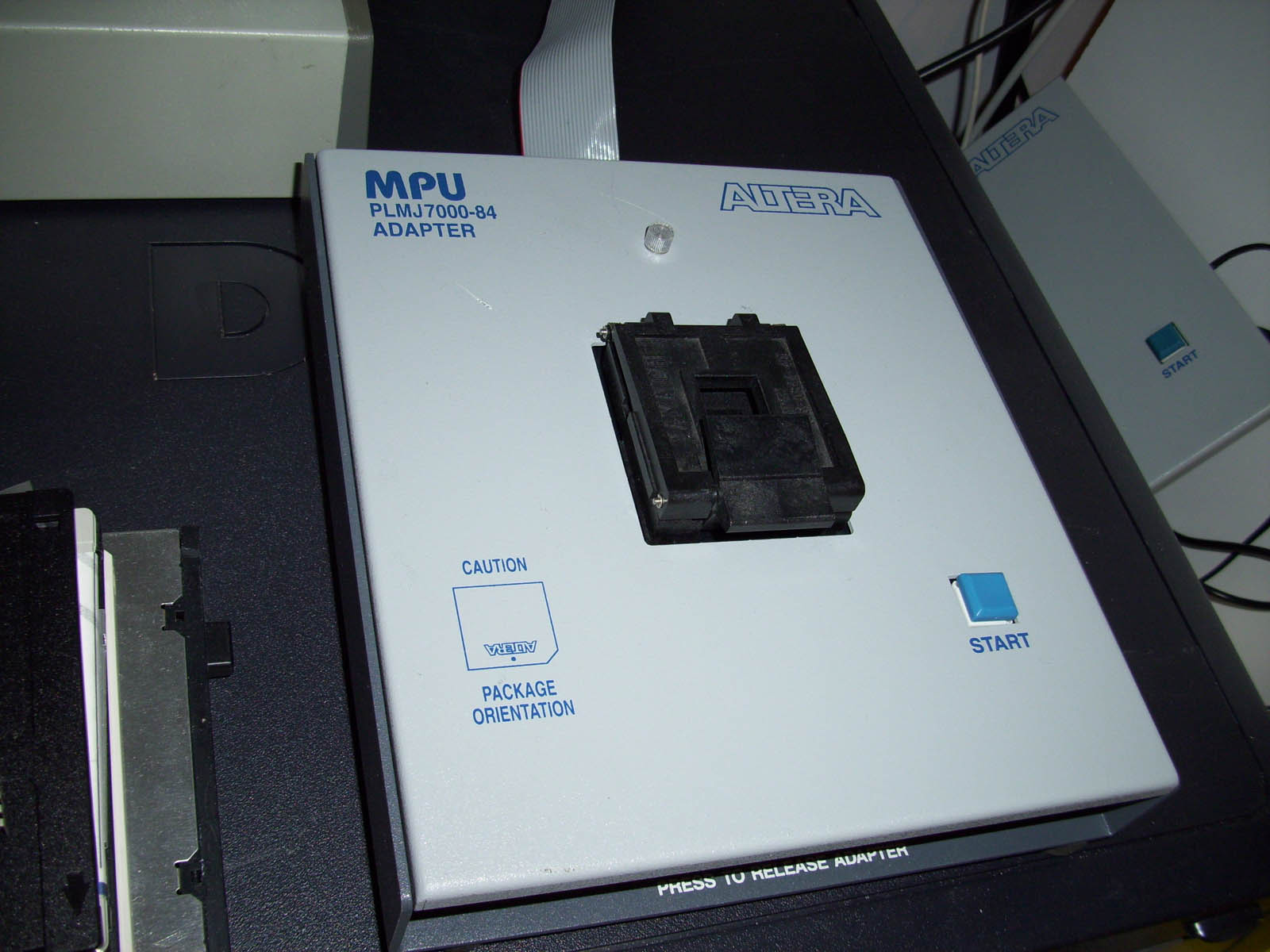
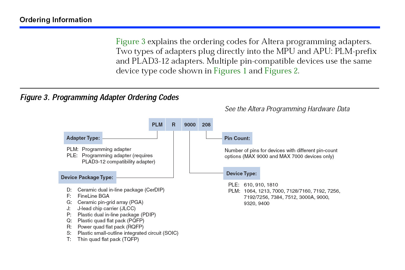
Altera MPU Adapter model numbers explained Shown below is the Adapter ordering info for Altera MPU adapters. This clearly indicates and explains the numbering system used for Altera MPU adapters.
You can also review the more recent "Altera Programming Hardware" document at the link below for a complete list of available MPU/APU adapters. http://www.altera.com/literature/ds/dspghd.pdf
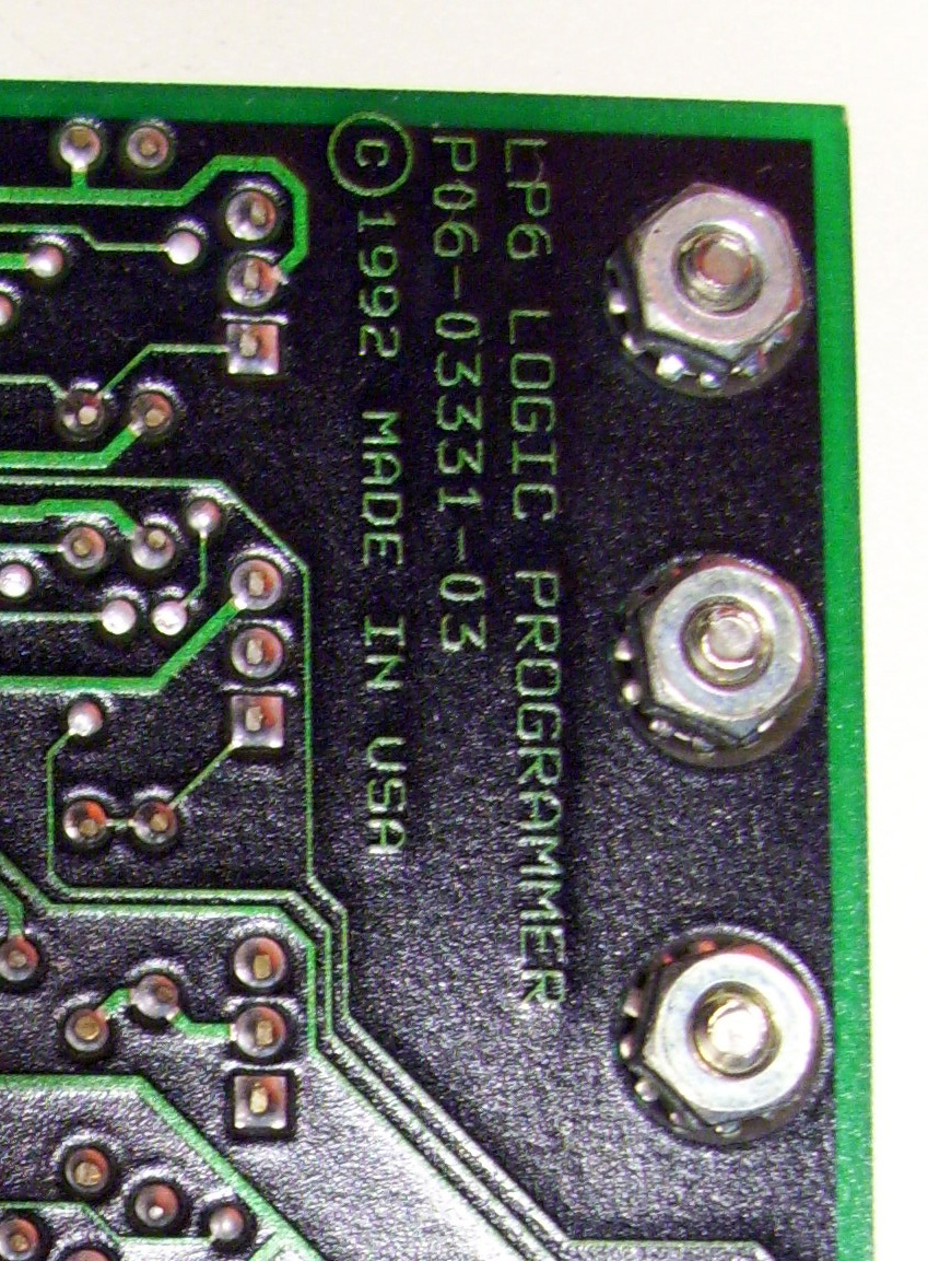
Altera LP6 Logic Programming Card
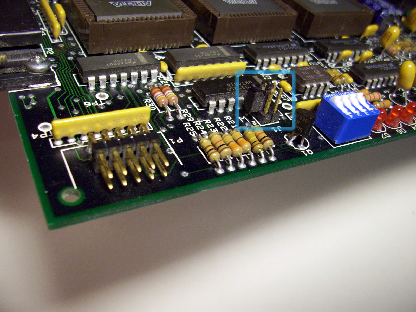
The LP6 Card has a set of DIP switches to set the Card address Bus channel. Usually this is a Hex Value of something like "280h" which is the Default setting. There is also a set up Jumper pins that I have not been able to identify as to their purpose. See the image above, the Juppers I have outlined with a Blue border. If you have any clue as to what the jumpers are for, please contact me through my contact page. I had the Idea to try and reverse Engineer one of these Cards, but have never develed into the possibility. I would first off have to check to see if the three 1810 CPLDs have their Security bit enabled. Chances are they have been, some day I might try that, but I guess the USB based "PL-APU" programmer would be a better unit to clone. You can view the Altera MAX Plus II "Getting Started" User's Manual for all the details and setup procedures for both the software and hardware of the PL-ASAP2 system. PDF download link shown below. http://www.digital-circuitry.com/FILES/Altera/MAX_PLUS_II_Getting_Started_Manual.pdf
If you're into the older Altera CPLD's you can Join my Altera Yahoo Group: http://groups.yahoo.com/group/AlteraMAX7000/
|
||
|
||